MM102225V1, Rev. B
61
STEPS
ACTION
MISCELLANEOUS
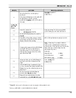
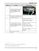
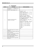
3.
Check the rear panel of the Cisco 3600
access server and observe whether the
Carrier Detect
LED is lit and the
LOCAL
and
REMOTE ALARM
LED’s are off.
4.
Connect the PC to the
CON
port of the
Cisco 3600 access server. This connector
is located on its front panel.
5.
Using address information given in the
regional IP Address Excel spreadsheet,
ping the MIS1 and MIS2 servers located
in the ROC. Commands and responses
are shown to the right.
buck40sas>ping 10.136.10.21
19
Sending 5, 100-byte ICMP Echoes to
10.136.8.10, timeout is 2 seconds:
!!!!!
Success rate is 100 percent (5/5), round-trip
min/avg/max = 8/8/12 ms
buck40sas>ping 10.136.10.21
Sending 5, 100-byte ICMP Echoes to
10.136.8.11, timeout is 2 seconds:
!!!!!
Success rate is 100 percent (5/5), round-trip
min/avg/max = 8/12/24 ms
buck40sas>
6.
Record the success or failure on
worksheet
20
.
19
"
Buck40
", where used in this manual, is only an example of the applicable code.
20
Refer to APPENDIX L - RECORDED DATA SHEET.
Summary of Contents for P5100 Series
Page 2: ...Installation Manual MM102225V1 Rev B Jul 05 Base Station Tower Site ...
Page 70: ...MM102225V1 Rev B 69 This page intentionally left blank ...
Page 72: ...MM102225V1 Rev B 71 This page intentionally left blank ...
Page 74: ...MM102225V1 Rev B 73 This page intentionally left blank ...
Page 76: ...MM102225V1 Rev B 75 This page intentionally left blank ...
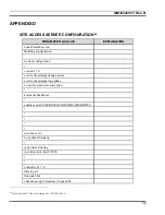
Page 82: ...MM102225V1 Rev B 81 PARAMETER VALUE EXPLANATION password cisco login end buck40sas ...
Page 92: ...MM102225V1 Rev B 91 This page intentionally left blank ...
Page 94: ...MM102225V1 Rev B 93 This page intentionally left blank ...
Page 96: ...MM102225V1 Rev B 95 This page intentionally left blank ...
Page 99: ...MM102225V1 Rev B 98 This page intentionally left blank ...

