background image


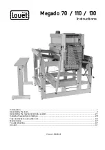
Megado 70 / 110 / 130 

Instructions


Introduction .......................................................................................................................................... 1


Assembling the loom ............................................................................................................................ 2


Assembling the mechanical dobby system ......................................................................................... 21


Installing the electronic interface ........................................................................................................ 29


Tips and tricks for using the loom ....................................................................................................... 33


Maintenance ...................................................................................................................................... 37


Trouble shooting ................................................................................................................................ 37


Contact .............................................................................................................................................. 41


Version: I-ME-EN-V3 


Summary of Contents for Megado 110

Page 1: ...ions Introduction 1 Assembling the loom 2 Assembling the mechanical dobby system 21 Installing the electronic interface 29 Tips and tricks for using the loom 33 Maintenance 37 Trouble shooting 37 Cont...

Page 2: ......

Page 3: ...t the activated warp threads are under greater tension and they become stretched If the warp is of an inelastic material and held at high tension the force required to treadle can be considerable With...

Page 4: ...nut again tightly Alternatively you can carefully tap against the bolt head with a hammer until the bolt head is secured into the wood Washers and spacers For the proper operation of the loom it is ve...

Page 5: ...er and barrel nut 4 bolts m6 x 70 mm with washer and barrel nut 4 carriage bolts m8 x 65 mm each with large washer two small washers and a cap nut 4 carriage bolts m8 x 50 mm each with a large ring an...

Page 6: ...nt connections of the side rails to the middle section are marked M M and N N Assemble the other hinged arm to side rail IMC in the manner described above Put the two remaining m8 x 65 mm carriage bol...

Page 7: ...side rails and make the connections I I J J F F and E E with the four remaining m8 x 130 mm bolts large washers and barrel nuts 3 Mounting the foot rail and cross member Take the foot rail GH out of...

Page 8: ...een the two vertical posts at the rear of the middle section Take four m6 x 70 mm bolts from the hardware bag and place them complete with their washers into the four holes of the middle posts Take th...

Page 9: ...resent Make sure that you assemble the section between the treadle arm and ball bearing in the correct sequence Consecutively slide the large washer the small washer and the bushing onto the bolt afte...

Page 10: ...Box B and the warp beam out of Box D Both are marked Q Slide the brake disk onto the longer shaft of the warp beam with the side marked Q facing the beam Use the four 5 x 40 mm screws to attach the di...

Page 11: ...barrel nuts point diagonally downwards Put the wooden pegs on side O of the back beam into the holes of the left back post Connection O O You will have to carefully bend the back post towards the outs...

Page 12: ...the holes for the connection to the cable are at the back side and on top Place a screw into the top hole of the treadle arm and while doing so adjust the connection rail to find the pilot hole The to...

Page 13: ...the steel bar on the right side of the loom which will move up and down with the treadle The knife is attached to a rotatable system of two connected disks The steel cable screwed onto the front disk...

Page 14: ...ok m6 x 60 mm with m6 barrel nut 1 brake cable 1 carriage bolt m8 x 50 mm with large washer 5 mm bushing small washer and cap nut 1 hook with a Texsolv cord Screw the ratchet onto the inside of the ri...

Page 15: ...install the cloth beam into the slots in the side rails of the loom Attach the beam cords to the screw heads of the cloth beam and the warp beam The Texsolv cords are cut at a joint between two loops...

Page 16: ...bolt Insert the m8 x 75 mm carriage bolt through the lower hole in the back post and slide the large washer and bushing onto it Tighten the cap nut and have the square part of the bolt head cut into t...

Page 17: ...interfere with the shaft cords Hook the cable loop onto the threaded hook while you use your other hand to push the pedal end down Again you could use some help to do this If you are working alone yo...

Page 18: ...19 cm long 2 springs with screw eye and cord 2 carriage bolts m8 x 75 mm with large washer 33 mm bushing large washer and cap nut Take the spring arms marked K and L out of box B Insert a carriage bol...

Page 19: ...ach spring arm Insert a screw through the second last hole on the other end of each cord and screw them into the holes of the backside of the front posts The eyes attached to the springs should be scr...

Page 20: ...se screw eyes can be used to tie up the cross sticks 11 Assembling the beater Open hardware Bag 5 from Box B 2 hinges for the beater uprights 2 bolts m6 x 75 mm with washer and barrel nut 2 carriage b...

Page 21: ...the side rail first and then the other Place the hinges into the grooves on the lower side rails Slide a washer onto both lag screws and insert the lag screws into the holes in the top beater bar If a...

Page 22: ...make a correction if necessary using the thin cardboard strips that you found in hardware bag 5 First check if the hinges protrude the same distance from the bottom of the uprights Take the beater by...

Page 23: ...eadling is programmed by inserting pegs into the holes of the program bars These pegs push the dobby hooks into their active position 1 Mounting the dobby head Open the hardware bag which contains 2 t...

Page 24: ...sert the bolt with one washer and bushing through the hole in the treadle and replace the first washer Insert the barrel nut into the hole in the front post on the left side of the loom and attach the...

Page 25: ...e of the screw hooks and screw it into the pilot hole on the middle post Loop the eye of the spring around the hook Guide the cord over the pulley above the treadle When you push the dobby treadle dow...

Page 26: ...sk are required for this assembly Remove the bolt from the disk and insert it from the inside through the hole on the front post Now slide the big washer the bushing the disk and the cap nut onto the...

Page 27: ...ide the bar run parallel and screw the remaining screw into the hole of the pulley bar and fasten the bar in its proper position Now tighten up the cap nut of the pulley bar completely 7 Adjusting the...

Page 28: ...ition of the disk by screwing one of the knurled nuts towards the tip of the hook and unscrewing the other the same number of turns 8 Attaching the treadle to the reversing disk Attach the spring onto...

Page 29: ...of program bars by pushing the grey connecting pegs on each side towards the inside and then pull them out of the chain Guide the program bars over the two wooden pulleys so that you can see the numb...

Page 30: ...ne at the same time You can place stickers on the side chain joints in order to number the program bars While you are weaving you can see which program bar is active by looking through the opening bet...

Page 31: ...ble North American European or British USB cable and 9 Pin serial cable to give you both possibilities for the connection with your computer 2 spare fuses Rare earth magnet 2 threaded rods 2 barrel nu...

Page 32: ...facing outwards Insert the threaded rods into the holes in the side of the middle section and screw them into the barrel nuts keeping the slot of the nuts in line with the rods Turn the rods by hand u...

Page 33: ...ad the newest drivers from the website www louet com select Spinning weaving Weaving looms Megado and follow the instructions described in the paragraph Louet Dobby USB Files If you use the USB cable...

Page 34: ...uter including the operating system on your computer and that you get the proper driver for the interface Computer requirements The requirements are very modest so both new and older computers can be...

Page 35: ...ur places Always place more heddles than you actually need on each shaft The sides of the shafts are made of spring steel and have a right angled bend at the ends The bended end fits in a hole in the...

Page 36: ...en the lifted upper shaft bar and the remaining ones to keep the shaft up when you release the treadle Now open the shaft at the bottom and slide the heddles onto the shaft bar Close the shaft again b...

Page 37: ...t during the beaming up of the warp In order to prevent the back part of the loom from being pulled up during the beaming of the warp you need to block the back part in its lowest position If your Meg...

Page 38: ...ht of the beater should be adjusted so that the warp threads rest in the bottom of the reed on the shuttle race This allows the shuttle race to properly support the shuttle The reed and lower reed sup...

Page 39: ...entally happen or if the dobby knife becomes stuck between the screw heads for some other reason you can easily undo this situation Turn the knob for manual operation 45 degrees and push down the shed...

Page 40: ...tance with a shaft follow this procedure To prevent working on the wrong shaft mark the shaft that needs adjustment with a piece of colored yarn on both ends Loosen the small bolts of the clamps that...

Page 41: ...n the height of the pedal The warp does not come loose from the warp beam when the warp is advanced Possible causes The brake pedal has to be pushed in further The warp tension you use for your projec...

Page 42: ...ule and replace the fuses You need a small screwdriver to do this See the installation instructions Be sure that you replace the fuse holder in the right direction showing the appropriate voltage afte...

Page 43: ...w the screw heads that protrude at the inside of the dobby hooks half a turn Otherwise remove a washer from the connection of the interface and the loom at both sides Take the ones in between the inte...

Reviews: