85
User Manual
5.5.2 XTE ALARM
Disables the XTE Alarm (Off) or selects the desired value. The default setting is
Off.
'MENU' + "ADVANCED SETTINGS" + 'ENTER' + "ALARMS" + 'ENTER' + "XTE
ALARM" + 'ENTER'
5.5.3 ANCHOR ALARM
This function allows inserting of the limit of anchor dragging: beyond that,
the alarm is activated. The chartplotter computes the distance between the current
GPS position and the GPS position saved at the activation of the anchor alarm in the
menu. If the computed distance exceeds the value set in the menu, the chartplotter
shows the alarm message and starts the acoustic alarm. The default setting is Off.
'MENU' + "ADVANCED SETTINGS" + 'ENTER' + "ALARMS" + 'ENTER' + "AN-
CHOR ALARM" + 'ENTER'
5.5.4 DEPTH ALARM
Specifies the depth or disables the Depth Alarm.
'MENU' + "ADVANCED SETTINGS" + 'ENTER' + "ALARMS" + 'ENTER' +
"DEPTH ALARM" + 'ENTER'
5.5.5 GROUNDING ALARM
The chartplotter is provided with a function that, by querying the map's data,
verifies potential danger to navigation due to shallow water, land, rocks, obstructions
and shoreline constructions. The maps are scanned periodically (every 10 seconds).
When the Grounding Alarm is active, the chartplotter scans an area in front
of the boat. This area is identified by a triangle drawn in front of the boat icon whose
direction is determined by the current boat heading. The length of the triangle is
user selectable and its angle is 30 degrees. If any of the above objects are found, the
chartplotter notifies the danger on a dedicated warning message box in the Ground-
ing Alarm Report page.
The Grounding Alarm is switched Off by default after a Master Reset. Once
the Grounding Alarm has been activated, a warning message is shown.
'MENU' + "ADVANCED SETTINGS" + 'ENTER' + "ALARMS" + 'ENTER' +
"GROUNDING ALARM" + 'ENTER'
Note
The Grounding Alarm function only operates with the new C-CARDs. It also affects the speed
of the redraw of the screen. If this function is not used it maybe disabled.
Summary of Contents for Compact 7 Plus
Page 14: ...16 User Manual...
Page 19: ...21 User Manual Fig 2 5 1 GPS Connection on Port 3...
Page 50: ...52 User Manual...
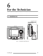
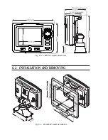
Page 87: ...89 User Manual 6 For the Technician 6 1 DIMENSIONS Fig 6 1 EXCALIBUR models Dimensions...
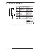
Page 92: ...94 User Manual Fig 6 4a GPS Connection on Port 3 for chartplotter with external GPS receiver...
Page 98: ...100 User Manual...


