Logosol Absolute Positioning Servo Drive LS-173AP
Doc # 712173008 / Rev. 1.06, 05/09/2002
Logosol, Inc.
••
1155 Tasman Drive
••
Sunnyvale, CA 94089 Tel: (408) 744-0974
••
www.logosolinc.com 14
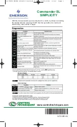
Encoder Input
The encoder interface accepts two square wave inputs, CH_A, CH_B and Index from an
incremental encoder. Ideally, these square waves are 50% duty cycle and e/-90
degrees out of phase. In any case, the time between encoder state transitions should be not
less than 2 µsec. With ideally formed encoder pulses, this would correspond to a 500-line
encoder (2000 counts/rev) rotating at 15,000 RPM.
CW MOTOR DIRECTION
All encoder inputs are with pull-up resistors 1K to +5V.
Encoder and Hall Inputs
Hall Inputs
Hall sensor inputs are placed on the same connector as encoder inputs. All hall sensors are
with pull-up resistors 1K to +5V. 60°/120° hall sensors may be used
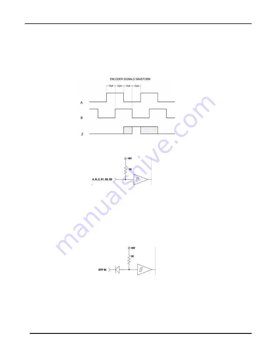
Stop input
STP IN is a stop input. If it is high or open the Power Driver will bi disabled (refer to
Status Bits
and LED
section of this document). STP IN is equipped with pull-up resistors 1K to +5V.
Stop Input
ADC
ADC is used as Absolute Positioning analog input. Input voltage is converted to an 8-bit A/D
value (refer to
Read Status
in
Command Description
section of this document). In absolute
positioning mode A/D value is compared with
Analog Target Value
(refer to
Absolute
Positioning mode
section of this document). If these two values are equal the motor will stop
smooth.