background image


14

3.5 

The operation of scanning 


1.


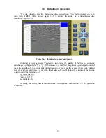
 Set the antenna power supply unit on the surface which is to scan and press the functional button 
«2» («Record», figure 3.5.1) for the record of a profile.  


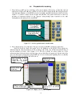
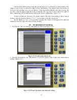
Figure 3.5.1. Measurements mode menu 


2.


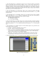
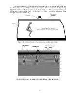
Smoothly move the antenna power supply unit on the planned trajectory. The search of the deep 

objects is possible to make at the mode, that is similar to the operation with metal detectors and mine 
detectors (figure 3.5.2). Antenna unit is possible to take of from a ground surface on a distance 5-10 
sm. It doest influence on the detection characteristics.  The device in equal intervals will radiate 
impulses and accept signals from the moving antenna unit of the device, that are reflected from 
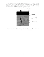
inhomogeneities of the scanning environment. The wave picture of the profile (radogramma) will be 
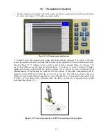
displayed on the BUOI screen while the device will be moving.  The reflection of point objects is 
displayed on the radogramma as hyperbola (a vertex of hyperbole is to correspond to the nearest point 
of objects of the antenna unit), reflection from the objects and layers are represented in tended 
horizontal lines (figure 3.5.3). 


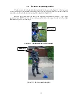
Figure 3.5.2. The moving trajectory of BAPP in searching of the dug objects 


Summary of Contents for OKO-2

Page 1: ...TRUCTION 140104 Russia Ramenskoe city Moscow region 100th Svirskoi Divizii st 11 tel fax 495 221 75 58 221 75 59 221 75 49 www logsys ru E mail info logsys ru Search kit ОКО 2 Operating Manual 2008г Logical systems ...

Page 2: ...et parameters of scanning 12 3 5 The operation of scanning 14 3 6 Detection of movement 16 3 7 General recommendations 19 3 8 Functioning of Start Stop button 19 3 9 Device Switching off and Disassembling 19 3 10 Viewing files 20 3 11 Settings 23 4 File Transfer from BUOI into a computer 25 5 Work with SK Око 2 along with using a notebook 28 6 Requirements on safe operation and electromagnetic com...

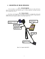
Page 3: ...ng designs and etc 2 2 Device structure The device is the monoblock The monoblock consists of two changeable receiving and transmitting antenna units BAPP control processing and indication unit BUOI folding handle rod SSHR off line power supply unit BP and sets of cables figure 2 2 1 Figure 2 2 1 Complex with BAPP II Off line power supply unit BP 3 8 12 Cable BP БП Folding handle rod Cable BAPP Ch...

Page 4: ...I cable connect BUOI and computer by interface Ethernet is stipulated in the device for connecting with the external computer and for forming three dimensional image 2 4 Marking and sealing The location of sealing wardrobe trunk packing BAPP I BAPP II BUOI and BP are represented in the Appendix 1 The seal of a wardrobe trunk is located on a long side part of wardrobe trunk in the upper right corne...

Page 5: ...nna unit are coming to output of ADC The sensitivity of the receiving device is not worse than 300 microvolt Transmitting unit The transmitting unit functionally consists of transmitting antenna unit pulse shaper and high voltage power supply unit The pulse shape at receipt of the starting pulse are to form the короткий перепад high voltage which is to activate the transmitting antenna The high vo...

Page 6: ...ter using Geascan32 software see The User s guide program Geoscan32 Autonomous power supply unit BP The autonomous power supply unit BP consists of ten Ni Mh accumulators and the accumulator indicator of the category which is control and indicate of the accumulator battery BP 3 8 12 is equipped with self recovering fuse The voltage is supply from BP to the BUOI and BAPP using power supply cable ...

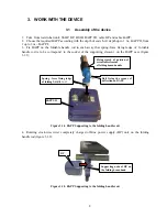
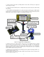
Page 7: ...od is to be correspond to the socket of the supporting element on the BAPP case figure 3 1 1 Figure 3 1 1 BAPP Supporting to the folding handle rod 4 Rotating clock wise twist completely charged off line power supply BP unit on the folding handle rod figure 3 1 2 Figure 3 1 2 BAPP Supporting to the folding handle rod BP Supporting node of BP on the folding beam hand Spring force fixing ledge of fo...

Page 8: ...elescopic of a folding handle rod up to the required value adjust the length of a f b h regarding the standing height of a person then rotating counterclockwise if looking from the side of a supporting element of BOUI tighten the fixing socket joint 9 Releasing the screw which fixes the turn of BUOI movement adjust the turn angle of BUOI in a relation to a handle rod figure 3 1 3 10 On releasing t...

Page 9: ... be on the belt and at the same time the freedom of moving SK is provided figure 3 2 2 BAPP is to be directed at the side of the scanning environment rejection _ 20 C from geometrical axis BAPP and is to be moved in a parallel surface of cargo close by or with a slight detachment up to 0 1 m from cargo Figure 3 2 1 The position of the device in the hands Figure 3 2 2 Device in operating position S...

Page 10: ...yed on the BUOI These signals are reflected from the objects and layers of the scanning zone in the way of black and white lines of various brightness colored lines figure 3 3 2 The wave picture of current written set of the reflected signals of the selected record time range as so called lines of signal is at the left side of the screen At that time Led indicator on the BAPP case is to be continu...

Page 11: ...he signal of direct transmitting figure 3 3 2 If after switching on the device the picture signal of the direct transmitting is below normal position using the following buttons и it is necessary to modify its position By the buttons и it is possible to change the contrast of radarogram For additional information use the program GeoScan32 Users manual 3 4 Set parameters of scanning 1 Press the key...

Page 12: ...educes to decrease in speed of scanning Recommend values of Accumulate 1 4 fast mode of scanning 8 32 basic mode of scanning 6 Press the functional key 5 Delay figure 3 4 2 to activate the options of a discrete regulation signal shift of a direct transmitting to the top profile smooth regulation of a shift is made with the help of the following buttons и in a Search mode and by the pointers и fix ...

Page 13: ... a distance 5 10 sm It doest influence on the detection characteristics The device in equal intervals will radiate impulses and accept signals from the moving antenna unit of the device that are reflected from inhomogeneities of the scanning environment The wave picture of the profile radogramma will be displayed on the BUOI screen while the device will be moving The reflection of point objects is...

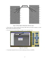
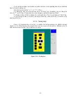
Page 14: ... for drawing label Drawing the label accompany by sound signal Program assign labels serial number 4 Press Esc for save file and Enter for approval of saving figure 3 5 4 Figure 3 5 4 Saving file 5 The Store button allows to save a file with information from screen of BUOI Local objects File name ...

Page 15: ...ine the quantity of the lines for averaging and changes by the pointers и If the value 1 is installed the processing is not performed if the value more than 1 the set quantity of the lines is to average and the averaged lines is to subtract from the again accepted lines For example this mode can be useful during the detection of the moving objects behind the wall and so on Recommendation Param det...

Page 16: ...6 2 there is a scheme detection of a moving person in the concrete tunnel On the figure 3 6 3 there is a detection radogramm of the moving person in the concrete tunnel Figure 3 6 2 A scheme detection of a moving person in the concrete tunnel Figure 3 6 3 Detection radogramm of the moving person in the concrete tunnel Antenna unit Iron concrete blockings The moving way of a person Tunnel Antenna u...

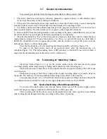
Page 17: ...ion of the moving objects complicated On the Figure 3 6 4 there is the detection radogramm of the moving animal dog The scanning was made through the brick wall of the adjoining room the thickness is 40 cm Figure 3 6 4 The detection radogramm of the moving animal dog that is scanning through the brick wall Antenna unit Brick wall Dog Reflected signals Movement way ...

Page 18: ...r recording the following profile Profile Figure 2 8 To input in the main choice menu of an operation mode press the functional key 5 Output Figure 2 8 The light emitting diode LED indicator on the BAPP case will not flash it means that the transmitting unit of the device will be switched on 3 8 Functioning of Start Stop button Start Stop button figure 3 1 3 is for the on line control of the start...

Page 19: ...1 Figure 3 10 1 Menu list of the stored files To open a file use и keys to chose a required file and press an Enter button If you press Esc now a menu for work with files will appear on the screen figure 3 10 2 which eanables either to delete this file or to delete all files or to format a hard drive of BUOI Warning BUOI hard drive formatting deletes all files on it Formatting is to be used only f...

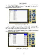
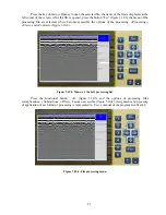
Page 20: ...ome accessible the options of the processing Processing View and Contract figure 3 10 4 Figure 3 10 3 Menu of the fail processing list Press the functional button 2 figure 3 10 3 and the options of processing files Amplication Subtraction Filter become accessible figure 3 10 4 Assignment and necessity of application of each kind of processing is represented in User s manual of the program GeoScan3...

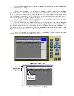
Page 21: ...igure 3 10 5 and then an Esc key a radarogramm is scaled that it could have space on a screen of BUOI Press a 4 functional key Sight rod Figure 3 10 5 and then an Esc key the oscillogramm corresponding to a signal of direct transmission and reflected signals figure 3 10 6 is displayed Keys and enable to move the oscillogramm on the file to the left or to the right and keys or enable to move up or ...

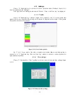
Page 22: ...palette files can be recorded with the help of a GeoScan 32 program and a sample of the palette colors blue color for a file selected Figure 3 11 1 List of colors palette By keys select a file with a required color palette Black and white palette is selected by a 1 functional key Press an Enter key enables to activate a selected palette for representation of profiles 3 11 2 Time settings Press a 3...

Page 23: ...ed by pressing Enter To change a value of timer counting out you should chose Use key and press an Enter key A time setting window is closed by pressing an Enter key while an Exit key is selected or by pressing an Esc key 3 11 3 Testing keys Press a 4 functional key Тest Key a display for testing operation of a BUOI keyboard figure 3 11 3 When the keys are pressed their view on a screen is colored...

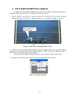
Page 24: ... a case of BUOI is shown in figure 4 1 Figure 4 1 Input connector linking up BUOI with PC 2 Switch on PC and Search kit OKO 2 Settings of network adapter and those of a computer Ethernet port must be the following IP Internet protocol address is TCP IP 10 0 0 100 subnetwork mask is 255 255 255 0 IP georadar address is 10 0 0 200 Warning After switching on BUOI do not exit a device operation mode s...

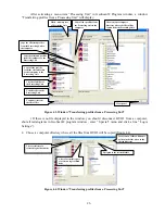
Page 25: ...size of Processing Unit The list of all files of the Processing Unit Copy all the profiles from the Processing Unit to the computer Copy the allocated profiles from the Processing Unit to the computer Copy the allocated profiles from the computer to the Processing Unit Copy all the profiles from the selected folder of the computer to the Processing Unit The election of computer directory where the...

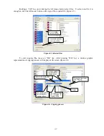
Page 26: ...After pressing OK key a window graphic representation of copying process will display on the screen figure 4 6 Figure 4 6 Copying process Key for coping the selected files The size and quantity of the selected files A window graphic representation of copying process Name of the copying files Prospective time before and of copying The quantity which has remained for copying of data The quantity whi...

Page 27: ...semble SK Oko 2 see item 3 1 of the present manual 2 Connect BUOI to a notebook with a connecting cable of PC through Ethernet port Input connector of a connecting cable on a case of BUOI is shown in figure 4 1 3 Pressing the button on a case of Power Unit switch on power supply of a device At this moment a LED indicator will start flashing on a case of PU and in a few seconds after automatic test...

Page 28: ...tary Certification 7 Technical maintenance 7 1 General instructions 1 During technical maintenance some preventive maintenance is performed to maintain the proper condition of the device and to provide its normal operation within the service life 8 years 2 Recommended frequency and types of technical maintenance 3 External examination before each running no damages incompatible with the operation ...

Page 29: ...al hours a charging process is switched on automatically If a red LED goes on flashing after the end of a test phase which lasts 10 seconds and does not turn to a steady shining light indicating a charging process that signifies that there is a malfunction of a battery and that the latter should be replaced by another one from the accessories ZIP 0 8 Routine Repair Routine repair is performed by a...

Page 30: ...led compartment 2 The temperature of a surrounding air during transportation must be from 30 С up to 50 С an the pressure from 84 до 106 7 кPа 630 800 mm of a mecury column 3 Placing and securing of a box with a device on transport facilities must provide a steady position during transportation lack of bias displacement and strikes and impacts of the devices by each other 4 Requirements of signs i...

Page 31: ...32 ...

Page 32: ...33 ...

Page 33: ...34 ...

Reviews: