


53
Icon
Port Name
Function
A
RS-485
communication
port
RS485_A port. It is the cable A. You can connect to
the control devices such as speed dome PTZ.
B
RS485_B.It is the cable B. You can connect to the
control devices such as speed dome PTZ.
2.2.8
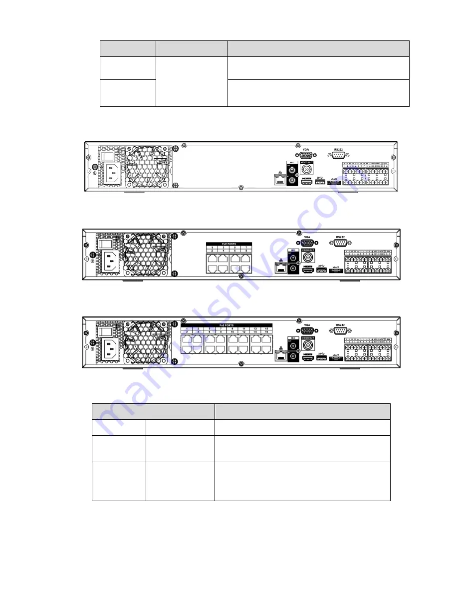
NVR44/44-8P/44-16P Series
The NVR44 series rear panel is shown as below. See Figure 2-28.
Figure 2-28
The NVR44-8P series rear panel is shown as below. See Figure 2-29.
Figure 2-29
The NVR44-16P series rear panel is shown as below. See Figure 2-30.
Figure 2-30
Please refer to the following sheet for detailed information.
Name
Function
Power switch
/
Power on-off button
Power
input
port
/
Input AC 100~240V.
MIC IN
Audio input port
Bidirectional talk input port. It is to receive the
analog audio signal output from the devices such
as microphone, pickup.
Summary of Contents for NVR4104W
Page 1: ...Network Video Recorder User s Manual V 1 8 0...
Page 41: ...29 Weight 1 5kg 2 5kg Exclude HDD Installation Desk installation...
Page 111: ...99 Figure 3 12 3 5 13 NVR78 Series Please refer to Figure 3 13 for connection sample...
Page 112: ...100 Figure 3 13 3 5 14 NVR78 16P Series Please refer to Figure 3 14 for connection sample...
Page 113: ...101 Figure 3 14 3 5 15 NVR78 RH Series Please refer to Figure 3 15 for connection sample...
Page 114: ...102 Figure 3 15 3 5 16 NVR70 Series Please refer to Figure 3 16 for connection sample...
Page 115: ...103 Figure 3 16 3 5 17 NVR70 R Series Please refer to Figure 3 17 for connection sample...
Page 116: ...104 Figure 3 17 3 5 18 NVR42V 8P Series Please refer to Figure 3 18 for connection sample...
Page 117: ...105 Figure 3 18...
Page 176: ...164 Figure 4 81 Figure 4 82...
Page 177: ...165 Figure 4 83 Figure 4 84...
Page 183: ...171 Figure 4 89 Figure 4 90...
Page 184: ...172 Figure 4 91 Figure 4 92...
Page 185: ...173 Figure 4 93 Figure 4 94...
Page 187: ...175 Figure 4 96 Figure 4 97...
Page 274: ...262 The motion detect interface is shown as in Figure 5 54 Figure 5 54 Figure 5 55...
Page 275: ...263 Figure 5 56 Figure 5 57 Figure 5 58...
Page 279: ...267 Figure 5 62 Figure 5 63...
Page 323: ...311...