


131
The PTZ operation is only valid in one-window mode.
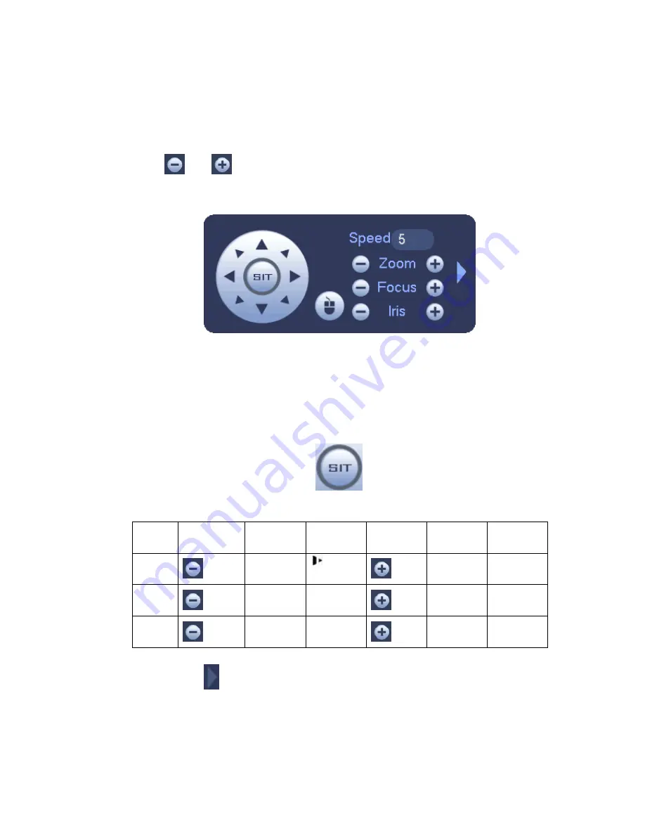
Here you can control PTZ direction, speed, zoom, focus, iris, preset, tour, scan, pattern aux function, light
and wiper, rotation and etc.
Speed is to control PTZ movement speed. The value ranges from 1 to 8.The speed 8 is faster than speed
1. You can use the remote control to click the small keyboard to set.
You can click
and
of the zoom, focus and iris to zoom in/out, definition and brightness.
The PTZ rotation supports 8 directions. If you are using direction buttons on the front panel, there are only
four directions: up/down/left/right.
Figure 4-39
In the middle of the eight direction arrows, there is a 3D intelligent positioning key. See Figure 4-40.
Please make sure your protocol supports this function and you need to use mouse to control.
Click this key, system goes back to the single screen mode. Drag the mouse in the screen to adjust
section size. The dragged zone supports 4X to 16X speeds. It can realize PTZ automatically. The smaller
zone you dragged, the higher the speed.
Figure 4-40
Name Function
key
function
Shortcut
key
Function
key
function
Shortcut
key
Zoom
Near
Far
Focus
Near
│
Far
►
│
Iris
close
Open
In Figure 4-39, click
to open the menu, you can set preset, tour, pattern, scan and etc. See
Figure 4-41.
Summary of Contents for NVR4104W
Page 1: ...Network Video Recorder User s Manual V 1 8 0...
Page 41: ...29 Weight 1 5kg 2 5kg Exclude HDD Installation Desk installation...
Page 111: ...99 Figure 3 12 3 5 13 NVR78 Series Please refer to Figure 3 13 for connection sample...
Page 112: ...100 Figure 3 13 3 5 14 NVR78 16P Series Please refer to Figure 3 14 for connection sample...
Page 113: ...101 Figure 3 14 3 5 15 NVR78 RH Series Please refer to Figure 3 15 for connection sample...
Page 114: ...102 Figure 3 15 3 5 16 NVR70 Series Please refer to Figure 3 16 for connection sample...
Page 115: ...103 Figure 3 16 3 5 17 NVR70 R Series Please refer to Figure 3 17 for connection sample...
Page 116: ...104 Figure 3 17 3 5 18 NVR42V 8P Series Please refer to Figure 3 18 for connection sample...
Page 117: ...105 Figure 3 18...
Page 176: ...164 Figure 4 81 Figure 4 82...
Page 177: ...165 Figure 4 83 Figure 4 84...
Page 183: ...171 Figure 4 89 Figure 4 90...
Page 184: ...172 Figure 4 91 Figure 4 92...
Page 185: ...173 Figure 4 93 Figure 4 94...
Page 187: ...175 Figure 4 96 Figure 4 97...
Page 274: ...262 The motion detect interface is shown as in Figure 5 54 Figure 5 54 Figure 5 55...
Page 275: ...263 Figure 5 56 Figure 5 57 Figure 5 58...
Page 279: ...267 Figure 5 62 Figure 5 63...
Page 323: ...311...