


161
Format: Click Format button, system pops up a dialogue box for you to confirm current operation.
System begins format process after you click the OK button.
Note:
System can not open config backup interface again if there is backup operation in the process.
System refreshes device when you go to the config backup every time and set current directory as
the root directory of the peripheral device.
If you go to the configuration backup interface first and then insert the peripheral device, please click
Refresh button to see the newly added device.
4.10.3
Backup Log
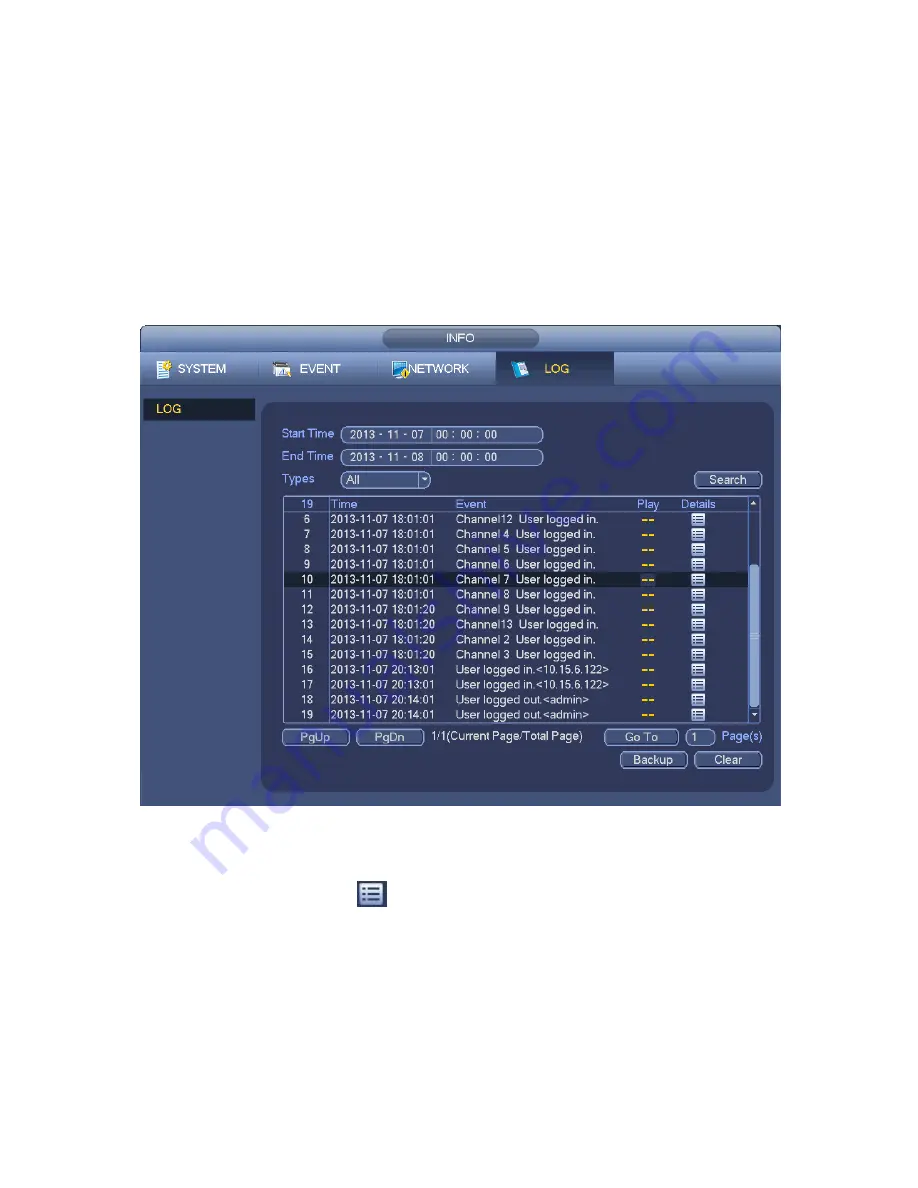
a) From Main menu->Info->Log, the interface is shown as below. See Figure 4-79.
Figure 4-79
b) Select log type and then set start time/end time, click Search button, you can see log time and
event information. Click
to view detailed log information.
c) Select log items you want to save and then click backup button, you can select a folder to save
them. Click Start to backup and you can see the corresponding dialogue box after the process is
finish.
4.10.4
USB Device Auto Pop-up
After you inserted the USB device, system can auto detect it and pop up the following dialogue box. It
allows you to conveniently backup file, log, configuration or update system. See Figure 4-80. Please refer
to chapter 4.10.1 file backup, chapter 4.10.3 backup log, chapter 4.10.2 import/export, and chapter 4.9.2
search for detailed information.
Summary of Contents for NVR4104W
Page 1: ...Network Video Recorder User s Manual V 1 8 0...
Page 41: ...29 Weight 1 5kg 2 5kg Exclude HDD Installation Desk installation...
Page 111: ...99 Figure 3 12 3 5 13 NVR78 Series Please refer to Figure 3 13 for connection sample...
Page 112: ...100 Figure 3 13 3 5 14 NVR78 16P Series Please refer to Figure 3 14 for connection sample...
Page 113: ...101 Figure 3 14 3 5 15 NVR78 RH Series Please refer to Figure 3 15 for connection sample...
Page 114: ...102 Figure 3 15 3 5 16 NVR70 Series Please refer to Figure 3 16 for connection sample...
Page 115: ...103 Figure 3 16 3 5 17 NVR70 R Series Please refer to Figure 3 17 for connection sample...
Page 116: ...104 Figure 3 17 3 5 18 NVR42V 8P Series Please refer to Figure 3 18 for connection sample...
Page 117: ...105 Figure 3 18...
Page 176: ...164 Figure 4 81 Figure 4 82...
Page 177: ...165 Figure 4 83 Figure 4 84...
Page 183: ...171 Figure 4 89 Figure 4 90...
Page 184: ...172 Figure 4 91 Figure 4 92...
Page 185: ...173 Figure 4 93 Figure 4 94...
Page 187: ...175 Figure 4 96 Figure 4 97...
Page 274: ...262 The motion detect interface is shown as in Figure 5 54 Figure 5 54 Figure 5 55...
Page 275: ...263 Figure 5 56 Figure 5 57 Figure 5 58...
Page 279: ...267 Figure 5 62 Figure 5 63...
Page 323: ...311...