


274
Figure 5-76
Please refer to the following sheet for detailed information.
Parameter
Function
Channel
Please select a channel from the dropdown list.
Pre-record
Please input pre-record time here. The value ranges from 0 to 30.
Redundancy Check the box here to enable redundancy function.
Please note this
function is null if there is only one HDD.
Snapshot
Check the box here to enable snapshot function.
Holiday
Check the box here to enable holiday function.
Setup
Click the Setup button, you can set record period. See Figure 5-75.
There are six periods in one day. If you do not check the date at the
bottom of the interface, current setup is for today only.
Please click Save button and then exit.
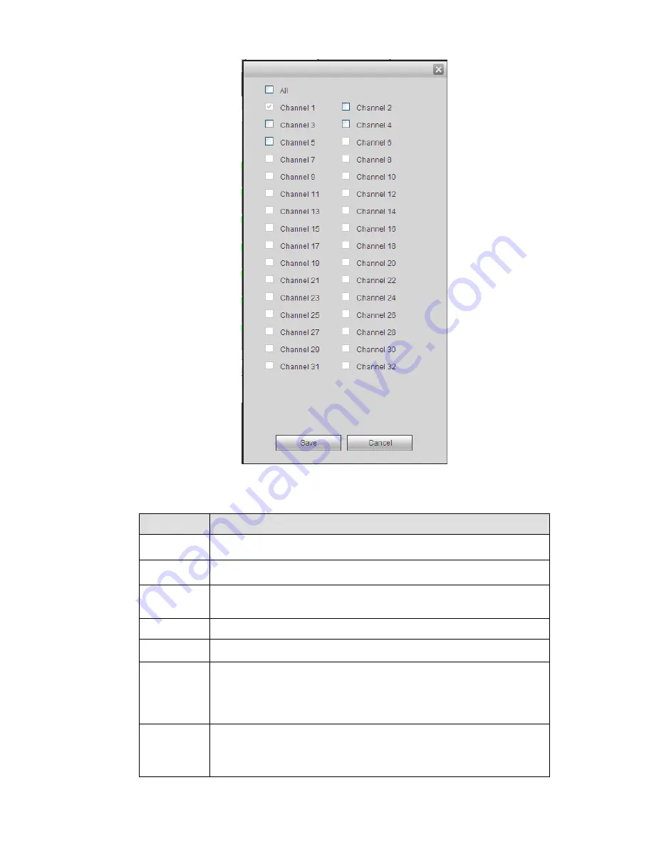
Copy
Copy function allows you to copy one channel setup to another. After
setting in channel, click Copy button, you can go to interface Figure
5-76. You can see current channel name is grey such as channel 1.
Now you can select the channel you wan to paste such as channel
Summary of Contents for NVR4104W
Page 1: ...Network Video Recorder User s Manual V 1 8 0...
Page 41: ...29 Weight 1 5kg 2 5kg Exclude HDD Installation Desk installation...
Page 111: ...99 Figure 3 12 3 5 13 NVR78 Series Please refer to Figure 3 13 for connection sample...
Page 112: ...100 Figure 3 13 3 5 14 NVR78 16P Series Please refer to Figure 3 14 for connection sample...
Page 113: ...101 Figure 3 14 3 5 15 NVR78 RH Series Please refer to Figure 3 15 for connection sample...
Page 114: ...102 Figure 3 15 3 5 16 NVR70 Series Please refer to Figure 3 16 for connection sample...
Page 115: ...103 Figure 3 16 3 5 17 NVR70 R Series Please refer to Figure 3 17 for connection sample...
Page 116: ...104 Figure 3 17 3 5 18 NVR42V 8P Series Please refer to Figure 3 18 for connection sample...
Page 117: ...105 Figure 3 18...
Page 176: ...164 Figure 4 81 Figure 4 82...
Page 177: ...165 Figure 4 83 Figure 4 84...
Page 183: ...171 Figure 4 89 Figure 4 90...
Page 184: ...172 Figure 4 91 Figure 4 92...
Page 185: ...173 Figure 4 93 Figure 4 94...
Page 187: ...175 Figure 4 96 Figure 4 97...
Page 274: ...262 The motion detect interface is shown as in Figure 5 54 Figure 5 54 Figure 5 55...
Page 275: ...263 Figure 5 56 Figure 5 57 Figure 5 58...
Page 279: ...267 Figure 5 62 Figure 5 63...
Page 323: ...311...