


250
5.8.2.7 PPPoE
The PPPoE interface is shown as in Figure 5-34.
Input the PPPoE user name and password you get from the IPS (internet service provider) and enable
PPPoE function. Please save current setup and then reboot the device to get the setup activated.
Device connects to the internet via PPPoE after reboot. You can get the IP address in the WAN from the
IP address column.
Please note, you need to use previous IP address in the LAN to login the device. Please go to the
IP address item to via the device current device information. You can access the client-end via
this new address.
Figure 5-34
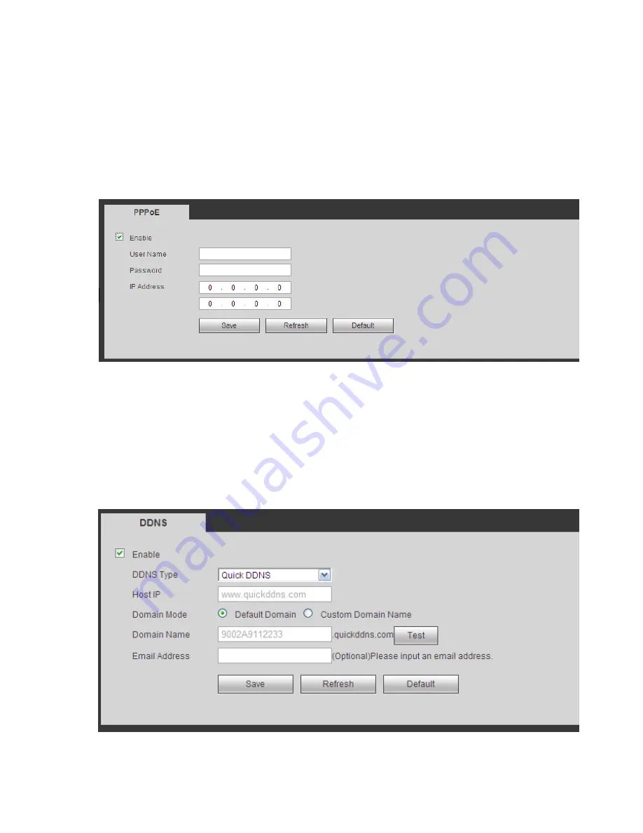
5.8.2.8 DDNS
The DDNS interface is shown as in Figure 5-35.
The DDNS is to set to connect the various servers so that you can access the system via the server.
Please go to the corresponding service website to apply a domain name and then access the system via
the domain. It works even your IP address has changed.
Please select DDNS from the dropdown list (Multiple choices). Before you use this function, please make
sure your purchased device support current function.
Figure 5-35
Summary of Contents for NVR4104W
Page 1: ...Network Video Recorder User s Manual V 1 8 0...
Page 41: ...29 Weight 1 5kg 2 5kg Exclude HDD Installation Desk installation...
Page 111: ...99 Figure 3 12 3 5 13 NVR78 Series Please refer to Figure 3 13 for connection sample...
Page 112: ...100 Figure 3 13 3 5 14 NVR78 16P Series Please refer to Figure 3 14 for connection sample...
Page 113: ...101 Figure 3 14 3 5 15 NVR78 RH Series Please refer to Figure 3 15 for connection sample...
Page 114: ...102 Figure 3 15 3 5 16 NVR70 Series Please refer to Figure 3 16 for connection sample...
Page 115: ...103 Figure 3 16 3 5 17 NVR70 R Series Please refer to Figure 3 17 for connection sample...
Page 116: ...104 Figure 3 17 3 5 18 NVR42V 8P Series Please refer to Figure 3 18 for connection sample...
Page 117: ...105 Figure 3 18...
Page 176: ...164 Figure 4 81 Figure 4 82...
Page 177: ...165 Figure 4 83 Figure 4 84...
Page 183: ...171 Figure 4 89 Figure 4 90...
Page 184: ...172 Figure 4 91 Figure 4 92...
Page 185: ...173 Figure 4 93 Figure 4 94...
Page 187: ...175 Figure 4 96 Figure 4 97...
Page 274: ...262 The motion detect interface is shown as in Figure 5 54 Figure 5 54 Figure 5 55...
Page 275: ...263 Figure 5 56 Figure 5 57 Figure 5 58...
Page 279: ...267 Figure 5 62 Figure 5 63...
Page 323: ...311...