


122
If you want to change system date and time, you can refer to general settings (Main
Menu->Setting->System->General). If you want to modify the channel name, please refer to the
display settings (Main Menu->Camera->CAM name)
Please refer to the following sheet for detailed information.
Tips
Preview drag: If you want to change position of channel 1 and channel 2 when you are
previewing, you can left click mouse in the channel 1 and then drag to channel 2, release mouse
you can switch channel 1 and channel 2 positions.
Use mouse middle button to control window split: You can use mouse middle button to switch
window split amount.
4.6.2
Preview control interface
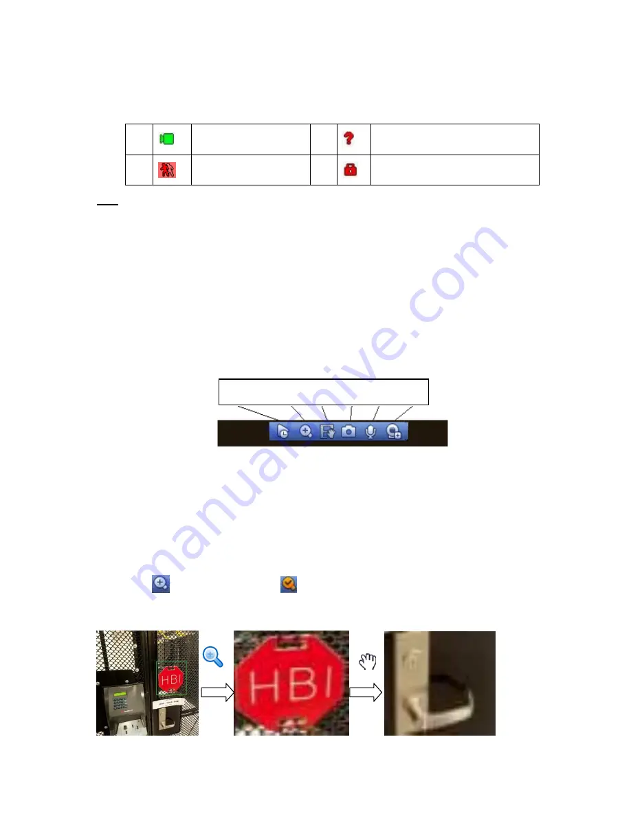
Move you mouse to the top centre of the video of current channel, you can see system pops up the
preview control interface. See Figure 4-28. If your mouse stays in this area for more than 6 seconds
and has no operation, the control bar automatically hides.
Figure 4-28 Digital Channel
1) Realtime playback
It is to playback the previous 5-60 minutes record of current channel.
Please go to the Main menu->Setting->->System->General to set real-time playback time.
System may pop up a dialogue box if there is no such record in current channel.
2) Digital zoom
It is to zoom in specified zone of current channel. It supports zoom in function of multiple-channel.
Click button
, the button is shown as
.
There are two ways for you to zoom in.
Drag the mouse to select a zone, you can view an interface show as Figure 4-29.
Figure 4-29
1
Recording status
3
Video loss
2
Motion detection
4
Camera lock
1 2 3 4 6 7
Summary of Contents for NVR4104W
Page 1: ...Network Video Recorder User s Manual V 1 8 0...
Page 41: ...29 Weight 1 5kg 2 5kg Exclude HDD Installation Desk installation...
Page 111: ...99 Figure 3 12 3 5 13 NVR78 Series Please refer to Figure 3 13 for connection sample...
Page 112: ...100 Figure 3 13 3 5 14 NVR78 16P Series Please refer to Figure 3 14 for connection sample...
Page 113: ...101 Figure 3 14 3 5 15 NVR78 RH Series Please refer to Figure 3 15 for connection sample...
Page 114: ...102 Figure 3 15 3 5 16 NVR70 Series Please refer to Figure 3 16 for connection sample...
Page 115: ...103 Figure 3 16 3 5 17 NVR70 R Series Please refer to Figure 3 17 for connection sample...
Page 116: ...104 Figure 3 17 3 5 18 NVR42V 8P Series Please refer to Figure 3 18 for connection sample...
Page 117: ...105 Figure 3 18...
Page 176: ...164 Figure 4 81 Figure 4 82...
Page 177: ...165 Figure 4 83 Figure 4 84...
Page 183: ...171 Figure 4 89 Figure 4 90...
Page 184: ...172 Figure 4 91 Figure 4 92...
Page 185: ...173 Figure 4 93 Figure 4 94...
Page 187: ...175 Figure 4 96 Figure 4 97...
Page 274: ...262 The motion detect interface is shown as in Figure 5 54 Figure 5 54 Figure 5 55...
Page 275: ...263 Figure 5 56 Figure 5 57 Figure 5 58...
Page 279: ...267 Figure 5 62 Figure 5 63...
Page 323: ...311...