


34
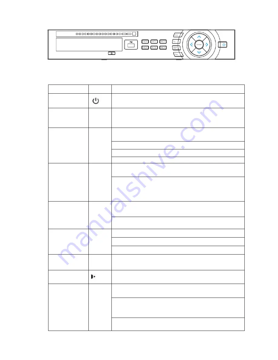
Figure 2-6
Please refer to the following sheet for front panel button information.
Name
Icon
Function
Power button
Power button, press this button for three seconds to boot up
or shut down NVR.
Shift
Shift
In textbox, click this button to switch between numeral,
English(Small/Capitalized),donation and etc.
Up/1
Down/4
、
Activate current control, modify setup, and then move up and
down.
Increase/decrease numeral.
Assistant function such as PTZ menu.
In text mode, input number 1/4 (English character G/H/I)
Left/2
Right/3
Shift current activated control,
When playback, click these buttons to control playback bar.
In text mode, input number 2(English character A/B/C)
/3(English character D/E/F)
.
ESC
ESC
Go to previous menu, or cancel current operation.
When playback, click it to restore real-time monitor mode.
Enter
ENTER
Confirm current operation
Go to default button
Go to menu
Record
REC
Manually stop/start recording, working with direction keys
or numeral keys to select the recording channel.
Slow play/8
Multiple slow play speeds or normal playback.
In text mode, input number 8 (English character T/U/V).
Assistant
Fn
One-window monitor mode, click this button to display
assistant function: PTZ control and image color.
Backspace function: in numeral control or text control, press
it for 1.5seconds to delete the previous character before the
cursor.
In motion detection setup, working with Fn and direction keys
to realize setup.
Summary of Contents for NVR4104W
Page 1: ...Network Video Recorder User s Manual V 1 8 0...
Page 41: ...29 Weight 1 5kg 2 5kg Exclude HDD Installation Desk installation...
Page 111: ...99 Figure 3 12 3 5 13 NVR78 Series Please refer to Figure 3 13 for connection sample...
Page 112: ...100 Figure 3 13 3 5 14 NVR78 16P Series Please refer to Figure 3 14 for connection sample...
Page 113: ...101 Figure 3 14 3 5 15 NVR78 RH Series Please refer to Figure 3 15 for connection sample...
Page 114: ...102 Figure 3 15 3 5 16 NVR70 Series Please refer to Figure 3 16 for connection sample...
Page 115: ...103 Figure 3 16 3 5 17 NVR70 R Series Please refer to Figure 3 17 for connection sample...
Page 116: ...104 Figure 3 17 3 5 18 NVR42V 8P Series Please refer to Figure 3 18 for connection sample...
Page 117: ...105 Figure 3 18...
Page 176: ...164 Figure 4 81 Figure 4 82...
Page 177: ...165 Figure 4 83 Figure 4 84...
Page 183: ...171 Figure 4 89 Figure 4 90...
Page 184: ...172 Figure 4 91 Figure 4 92...
Page 185: ...173 Figure 4 93 Figure 4 94...
Page 187: ...175 Figure 4 96 Figure 4 97...
Page 274: ...262 The motion detect interface is shown as in Figure 5 54 Figure 5 54 Figure 5 55...
Page 275: ...263 Figure 5 56 Figure 5 57 Figure 5 58...
Page 279: ...267 Figure 5 62 Figure 5 63...
Page 323: ...311...