


158
Mark Manager
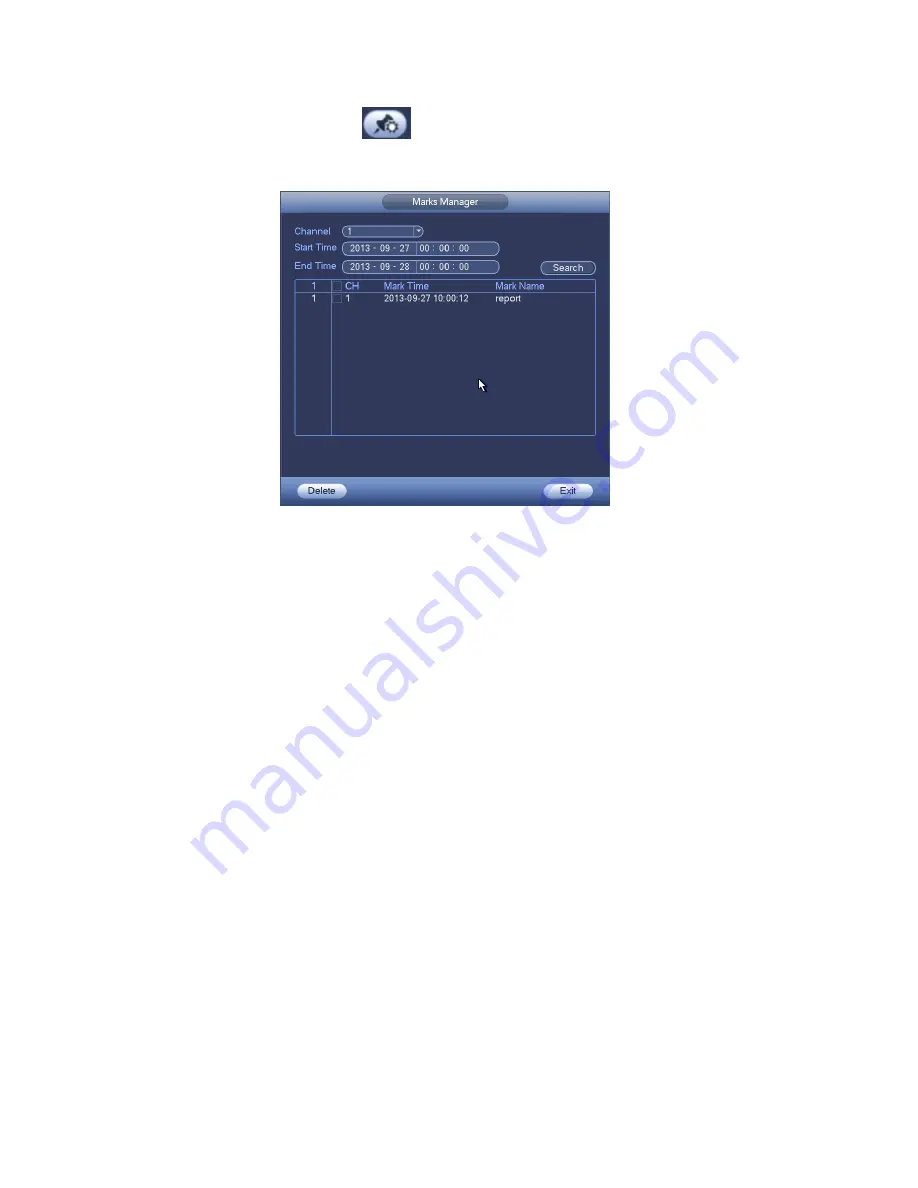
Click the mark manager button
on the Search interface (Figure 4-71); you can go to Mark
Manager interface. See Figure 4-75. System can manage all the record mark information of current
channel by default. You can view all mark information of current channel by time.
Figure 4-75
Modify
Double click one mark information item, you can see system pops up a dialogue box for you to change
mark information. You can only change mark name here.
Delete
Here you can check the mark information item you want to delete and then click Delete button, you can
remove one mark item. .
Note
After you go to the mark management interface, system needs to pause current playback. System
resume playback after you exit mark management interface.
If the mark file you want to playback has been removed, system begin playbacking from the first file
in the list.
4.9.3
Picture Playback
a) From Main menu->Search, or on the preview interface right click mouse, you can go to Figure
4-71.
b) At the top right pane, you can check the box to select picture and then select playback interval.
c) Please refer to chapter 4.9.2 to select picture you want to view.
4.10 Backup
4.10.1
File Backup
In this interface, you can backup record file to the USB device.
a) Connect USB burner, USB device or portable HDD and etc to the device.
b) From Main menu->Backup, you can go to the Backup interface. See Figure 4-76
Summary of Contents for NVR4104W
Page 1: ...Network Video Recorder User s Manual V 1 8 0...
Page 41: ...29 Weight 1 5kg 2 5kg Exclude HDD Installation Desk installation...
Page 111: ...99 Figure 3 12 3 5 13 NVR78 Series Please refer to Figure 3 13 for connection sample...
Page 112: ...100 Figure 3 13 3 5 14 NVR78 16P Series Please refer to Figure 3 14 for connection sample...
Page 113: ...101 Figure 3 14 3 5 15 NVR78 RH Series Please refer to Figure 3 15 for connection sample...
Page 114: ...102 Figure 3 15 3 5 16 NVR70 Series Please refer to Figure 3 16 for connection sample...
Page 115: ...103 Figure 3 16 3 5 17 NVR70 R Series Please refer to Figure 3 17 for connection sample...
Page 116: ...104 Figure 3 17 3 5 18 NVR42V 8P Series Please refer to Figure 3 18 for connection sample...
Page 117: ...105 Figure 3 18...
Page 176: ...164 Figure 4 81 Figure 4 82...
Page 177: ...165 Figure 4 83 Figure 4 84...
Page 183: ...171 Figure 4 89 Figure 4 90...
Page 184: ...172 Figure 4 91 Figure 4 92...
Page 185: ...173 Figure 4 93 Figure 4 94...
Page 187: ...175 Figure 4 96 Figure 4 97...
Page 274: ...262 The motion detect interface is shown as in Figure 5 54 Figure 5 54 Figure 5 55...
Page 275: ...263 Figure 5 56 Figure 5 57 Figure 5 58...
Page 279: ...267 Figure 5 62 Figure 5 63...
Page 323: ...311...