


151
c) Click Add button to complete holiday setup. Now you can enable holiday setup and then click
Apply button.
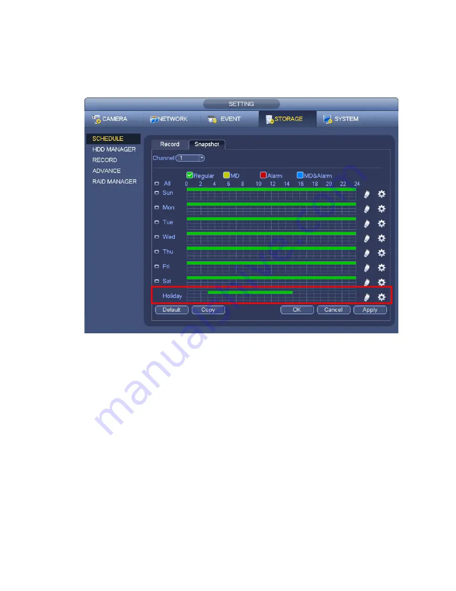
d) From Main menu->setting->Storage->schedule, you can go to schedule interface. See Figure
4-70. Now you can set period and record type of holiday time. Please refer to chapter 4.8.2.1 for
detailed setup information.
Figure 4-70
e) Click OK button to set holiday record setup.
4.8.6.2 Holiday Snapshot
Set Holiday date first. Please refer to step a) to step c) of chapter 4.8.6.1.
From Main menu->Setting->Storage->Schedule, you can go to schedule interface. See Figure 4-70. Click
Holiday item to set snapshot period.
Set holiday snapshot type (Trigger/Regular). Please refer to chapter 4.8.2.2 or chapter 4.8.3.2.
4.8.7
Other Record/Snapshot
Motion detect&Alarm record or snapshot, please refer to chapter 4.8.4.
Video loss or tampering record or snapshot function, please refer to chapter 4.8.3.
4.9 Playback and Search
4.9.1
Real-time Playback
Please refer to chapter 4.6.2 for real-time playback information.
Summary of Contents for NVR4104W
Page 1: ...Network Video Recorder User s Manual V 1 8 0...
Page 41: ...29 Weight 1 5kg 2 5kg Exclude HDD Installation Desk installation...
Page 111: ...99 Figure 3 12 3 5 13 NVR78 Series Please refer to Figure 3 13 for connection sample...
Page 112: ...100 Figure 3 13 3 5 14 NVR78 16P Series Please refer to Figure 3 14 for connection sample...
Page 113: ...101 Figure 3 14 3 5 15 NVR78 RH Series Please refer to Figure 3 15 for connection sample...
Page 114: ...102 Figure 3 15 3 5 16 NVR70 Series Please refer to Figure 3 16 for connection sample...
Page 115: ...103 Figure 3 16 3 5 17 NVR70 R Series Please refer to Figure 3 17 for connection sample...
Page 116: ...104 Figure 3 17 3 5 18 NVR42V 8P Series Please refer to Figure 3 18 for connection sample...
Page 117: ...105 Figure 3 18...
Page 176: ...164 Figure 4 81 Figure 4 82...
Page 177: ...165 Figure 4 83 Figure 4 84...
Page 183: ...171 Figure 4 89 Figure 4 90...
Page 184: ...172 Figure 4 91 Figure 4 92...
Page 185: ...173 Figure 4 93 Figure 4 94...
Page 187: ...175 Figure 4 96 Figure 4 97...
Page 274: ...262 The motion detect interface is shown as in Figure 5 54 Figure 5 54 Figure 5 55...
Page 275: ...263 Figure 5 56 Figure 5 57 Figure 5 58...
Page 279: ...267 Figure 5 62 Figure 5 63...
Page 323: ...311...