


231
In section 2, left click the channel name you want to view, you can see the corresponding video in current
window.
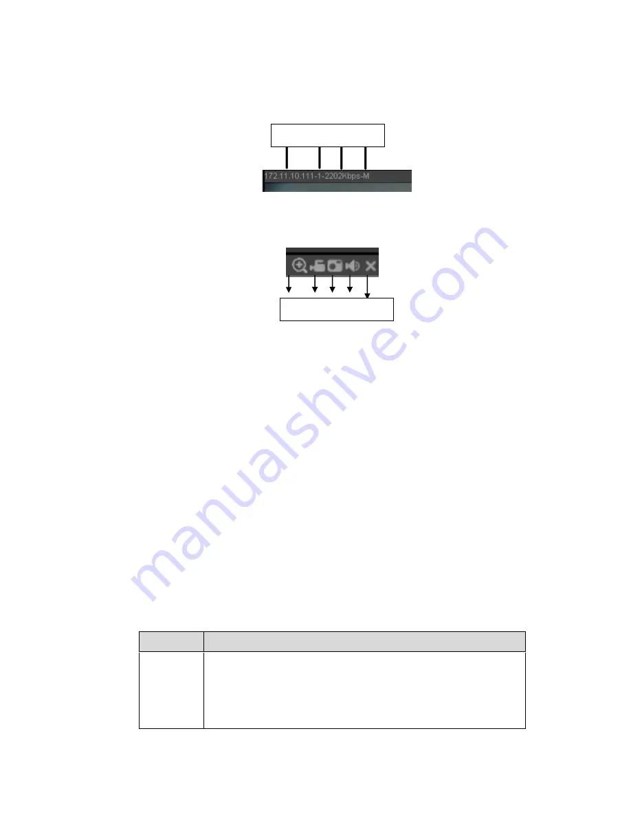
On the top left corner, you can view device IP(172.11.10.11), channel number(1), network monitor bit
stream(2202Kbps) and stream type(M=main stream, S=sub stream). See Figure 5-10.
Figure 5-10
On the top right corner, there are six unction buttons. See Figure 5-11.
Figure 5-11
1: Digital zoom: Click this button and then left drag the mouse in the zone to zoom in. right click
mouse system restores original status.
2: Local record. When you click local record button, the system begins recording and this button
becomes highlighted. You can go to system folder RecordDownload to view the recorded file.
3: Snapshot picture. You can snapshot important video. All images are memorized in system client
folder PictureDownload (default).
4: Audio :Turn on or off audio.(It has no relationship with system audio setup )
5: Close video.
5.4 PTZ
Before PTZ operation, please make sure you have properly set PTZ protocol. (Please refer to chapter
5.8.5.10).
There are eight direction keys. In the middle of the eight direction keys, there is a 3D intelligent
positioning key.
Click 3D intelligent positioning key, system goes back to the single screen mode. Drag the mouse in the
screen to adjust section size. It can realize PTZ automatically.
Please refer to the following sheet for PTZ setup information.
Parameter Function
Scan
Select Scan from the dropdown list.
Click Set button, you can set scan left and right limit.
Use direction buttons to move the camera to you desired location
and then click left limit button. Then move the camera again and
then click right limit button to set a right limit.
1 2 3 4 5
1 2 3 4
Summary of Contents for NVR4104W
Page 1: ...Network Video Recorder User s Manual V 1 8 0...
Page 41: ...29 Weight 1 5kg 2 5kg Exclude HDD Installation Desk installation...
Page 111: ...99 Figure 3 12 3 5 13 NVR78 Series Please refer to Figure 3 13 for connection sample...
Page 112: ...100 Figure 3 13 3 5 14 NVR78 16P Series Please refer to Figure 3 14 for connection sample...
Page 113: ...101 Figure 3 14 3 5 15 NVR78 RH Series Please refer to Figure 3 15 for connection sample...
Page 114: ...102 Figure 3 15 3 5 16 NVR70 Series Please refer to Figure 3 16 for connection sample...
Page 115: ...103 Figure 3 16 3 5 17 NVR70 R Series Please refer to Figure 3 17 for connection sample...
Page 116: ...104 Figure 3 17 3 5 18 NVR42V 8P Series Please refer to Figure 3 18 for connection sample...
Page 117: ...105 Figure 3 18...
Page 176: ...164 Figure 4 81 Figure 4 82...
Page 177: ...165 Figure 4 83 Figure 4 84...
Page 183: ...171 Figure 4 89 Figure 4 90...
Page 184: ...172 Figure 4 91 Figure 4 92...
Page 185: ...173 Figure 4 93 Figure 4 94...
Page 187: ...175 Figure 4 96 Figure 4 97...
Page 274: ...262 The motion detect interface is shown as in Figure 5 54 Figure 5 54 Figure 5 55...
Page 275: ...263 Figure 5 56 Figure 5 57 Figure 5 58...
Page 279: ...267 Figure 5 62 Figure 5 63...
Page 323: ...311...