


272
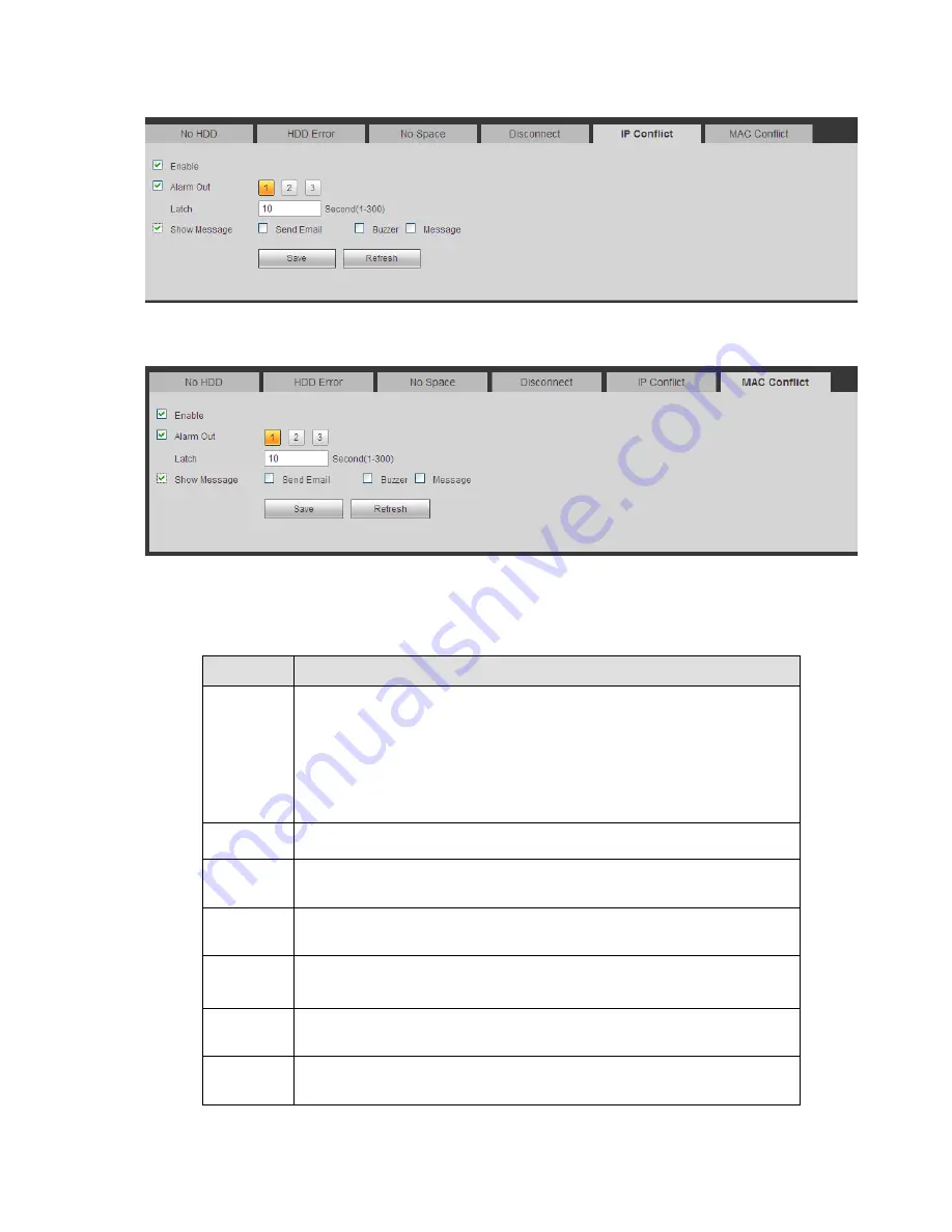
Figure 5-72
Figure 5-73
Please refer to the following sheet for detailed information.
Parameter Function
Event
Type
The abnormal events include: No disk, disk error, disk no space, net
disconnection, IP conflict and MAC conflict.
You can set one or more items here.
Less than: You can set the minimum percentage value here (For disk
not space only). The device can alarm when capacity is not sufficient.
You need to draw a circle to enable this function.
Enable
Check the box here to enable selected function.
Alarm Out
Please select corresponding alarm output channel when an alarm
occurs. You need to check the box to enable this function.
Latch
The alarm output can delay for the specified time after an alarm stops.
The value ranges from 1s to 300s.
Show
message
System can pop up a message to alarm you in the local host screen if
you enabled this function.
Alarm
upload
System can upload the alarm signal to the centre (Including alarm
centre.
Send
Email
If you enabled this function, System can send out an email to alert you
when an alarm occurs.
Summary of Contents for NVR4104W
Page 1: ...Network Video Recorder User s Manual V 1 8 0...
Page 41: ...29 Weight 1 5kg 2 5kg Exclude HDD Installation Desk installation...
Page 111: ...99 Figure 3 12 3 5 13 NVR78 Series Please refer to Figure 3 13 for connection sample...
Page 112: ...100 Figure 3 13 3 5 14 NVR78 16P Series Please refer to Figure 3 14 for connection sample...
Page 113: ...101 Figure 3 14 3 5 15 NVR78 RH Series Please refer to Figure 3 15 for connection sample...
Page 114: ...102 Figure 3 15 3 5 16 NVR70 Series Please refer to Figure 3 16 for connection sample...
Page 115: ...103 Figure 3 16 3 5 17 NVR70 R Series Please refer to Figure 3 17 for connection sample...
Page 116: ...104 Figure 3 17 3 5 18 NVR42V 8P Series Please refer to Figure 3 18 for connection sample...
Page 117: ...105 Figure 3 18...
Page 176: ...164 Figure 4 81 Figure 4 82...
Page 177: ...165 Figure 4 83 Figure 4 84...
Page 183: ...171 Figure 4 89 Figure 4 90...
Page 184: ...172 Figure 4 91 Figure 4 92...
Page 185: ...173 Figure 4 93 Figure 4 94...
Page 187: ...175 Figure 4 96 Figure 4 97...
Page 274: ...262 The motion detect interface is shown as in Figure 5 54 Figure 5 54 Figure 5 55...
Page 275: ...263 Figure 5 56 Figure 5 57 Figure 5 58...
Page 279: ...267 Figure 5 62 Figure 5 63...
Page 323: ...311...