April 17, 2000
Man ual Versio n 1.0
A.6
will be flawed because clearances will not be taken up by the counterbalance.
Now we press the “CALIBRATE SLIDE” softkey to perform the actual slide calibration as described in
section 4.2.2.1 using the wire speed from the transducer nameplate (9.219 in this example) and an
orientation of 0.
After calibration, the “Present Position” field in the slide configuration screen should display the number
we just entered for the calibration position to the nearest thousandth. In other words, if we had entered
14.074 inches for our calibration position, the present position should read 14.073 to 14.075 inches.
Now we take the press back to the top of the stroke. With the slide adjust switch on, “JOG UP” and
“JOG DOWN” softkeys should be displayed in the slide configuration screen.
Using the jog keys, we raise the slide to verify that the upper mechanical limit switch works correctly.
Be
very careful
as the slide approaches the true maximum shut height (16.000 inches in this example)
as the upper limit switch may be inoperative or misadjusted. Replace or adjust the limit switch as
necessary.
In the same way, we verify that the lower mechanical limit switch works correctly. Again for emphasis,
be
very careful
as the slide approaches the true minimum shut height (12.500 inches in this example) as
the lower limit switch may be inoperative or misadjusted. Replace or adjust the limit switch as
necessary.
If desired, the “Upper Limit” and “Lower Limit” can be set to be more restrictive than the actual
minimum and maximum shut heights.
Next we go to the “Mode” line of the system and turn it “ON” by cycling through the choices with the
“CHANGE MODE” softkey.
The last thing we must do is verify that the “Pulse Distance” and “Pulse Time” settings work for our
press. These settings affect how automatic adjustment works. We hit “Exit” twice to return to the “Auto
Sets” screen and hit the “RESET ERROR” softkey, if necessary, to clear errors in the slide adjust
system. The slide setpoint should also be set to some reasonable value. In this example, the slide should
still be at our calibration point of 14.074 inches. We set the slide setpoint to 14.000 inches.
After clearing errors, if present, we go back to the slide configuration screen. With the slide adjust
switch on, we should see “JOG UP”, JOG DOWN”, and “AUTO ADJUST” softkeys. Again we check
to make sure the slide is properly counterbalanced. If it is not then the following tests will be
meaningless. An under or over counterbalanced slide will not move the same way that a properly
counterbalanced slide will.
For fine adjustment purposes, a momentary push of the “JOG UP” or “JOG DOWN” key will “pulse”
the slide motor starter for “Pulse Time” seconds. We hit a jog key to see how far the slide moves with
one pulse. Ideally, it should take around 2 pulses to move .001 inch. We hit the “JOG DOWN” key and
find that it takes 5 pulses to move the slide .001 inch - too many. We change the “Pulse Time” value to
“.04" sec. Repeating the test, we find that it now takes 1 to 2 pulses to move .001 inch - an acceptable
value.
Summary of Contents for OmniLink 5000
Page 5: ...April 17 2000 Manual Versio n 1 0 iv...
Page 38: ...April 17 2000 Manual Versio n 1 0 4 14...
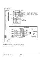
Page 63: ...April 17 2000 Manual Versio n 1 0 B 2 Figure B 2 Typical Cushion Wiring Diagram...
Page 64: ...April 17 2000 Manual Versio n 1 0 B 3 Figure B 3 Conceptual Dual Resolver Mounting...
Page 65: ...April 17 2000 Manual Versio n 1 0 B 4 Figure B 4 Typical AMCI Dual Resolver Wiring Diagram...
Page 66: ...April 17 2000 Manual Versio n 1 0 B 5 Figure B 5 Typical GEMCO Dual Resolver Wiring Diagram...
Page 67: ...April 17 2000 Manual Versio n 1 0 B 6 Figure B 6 Conceptual Linear Transducer Mounting...
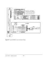
Page 68: ...April 17 2000 Manual Versio n 1 0 B 7 Figure B 7 Typical GEMCO Linear Transducer Wiring...
Page 71: ...April 17 2000 Manual Versio n 1 0 B 10...


