April 17, 2000
Man ual Versio n 1.0
A.2
Note that units to the right of the number are also an editable parameter. When the editing cursor is
placed on the Max Die Weight units, we can press the “CHANGE UNIT” softkey to get a list of
supported units. The units can be pounds, kilograms, tons, or metric tons. We are using pounds. Note
that the units for minimum and maximum die weight will always be the same, but will not necessarily be
the same as the “Display Weight As” units. This allows us to enter the die weights in whatever units the
name plate uses, but operate the press in a different set of units.
“Min. Die Weight” for a counterbalance should typically be 0. This represents no tooling on the upper
die.
The “Display Weight As” units we set to pounds.
The “Fault Time” we leave at 20 seconds.
The “Tolerance” is left at the default 2 psi.
Finally, we go back to the “Mode” line and use the “CHANGE MODE” key to toggle the mode to
“ON”. The “Auto Sets” operation screen can now be used to set the air pressure or die weight. See
section 5.2 for operation details.
Section A.2
Example Cushion Configuration
This example assumes the cushion system has been wired to the option board at “AS2". First, some
information needs to be gathered.
From the press manual or cushion information plate we find that the effective area of the cushion is 100
square inches and the maximum operating pressure is 90 psi. This means that the cushion will exert 100
pounds of force for every 1 psi of cushion pressure (100 square inches * 1 pound per square inch). We
also found out from experimentation that is takes about 3 psi to initially move the cushion, and that the
cushion just starts to fall at 2 psi. This tells us that approximately 2 psi is required to overcome the
weight of the cushion piston and pressure plate.
The pressure transducer installed on the system is a Setra model C206 that has a pressure range of 0 to
250 psi and an output of 4 to 20 ma.
A type “B” integrated valve controls the pressure (see section 3.1 for a discussion of valve types).
Now we go to the “Auto Sets” screen and with the RUN/PROG switch in PROG hit the “CONFIGURE”
softkey. After typing the configuration code, we press the “CONFIGURE AIR” softkey.
Since the cushion is wired in at “AS2", if the slot reported on the screen in not already “AS2", we hit the
“NEXT AIR SLOT” softkey until it is. The hardware detected should be “Fill/Dump”.
The first thing we must configure is the “Name” of the system. The cursor should already be on the
“Name” line so we check to see if the name is already “Cushion #1". If not, the “CHANGE NAME”
softkey allows us to cycle through the systems.
Summary of Contents for OmniLink 5000
Page 5: ...April 17 2000 Manual Versio n 1 0 iv...
Page 38: ...April 17 2000 Manual Versio n 1 0 4 14...
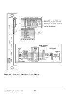
Page 63: ...April 17 2000 Manual Versio n 1 0 B 2 Figure B 2 Typical Cushion Wiring Diagram...
Page 64: ...April 17 2000 Manual Versio n 1 0 B 3 Figure B 3 Conceptual Dual Resolver Mounting...
Page 65: ...April 17 2000 Manual Versio n 1 0 B 4 Figure B 4 Typical AMCI Dual Resolver Wiring Diagram...
Page 66: ...April 17 2000 Manual Versio n 1 0 B 5 Figure B 5 Typical GEMCO Dual Resolver Wiring Diagram...
Page 67: ...April 17 2000 Manual Versio n 1 0 B 6 Figure B 6 Conceptual Linear Transducer Mounting...
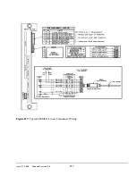
Page 68: ...April 17 2000 Manual Versio n 1 0 B 7 Figure B 7 Typical GEMCO Linear Transducer Wiring...
Page 71: ...April 17 2000 Manual Versio n 1 0 B 10...


