April 17, 2000
Man ual Versio n 1.0
4.6
choices are pounds (lbs), kilograms (Kgs), tons, and metric tons (Mtons). Note
that the display unit can be changed at any time and is independent of the units
used for minimum and maximum trip point. If a job was stored in tons, and this
unit is changed to pounds, the stored job will still be correct. For example, if 2
tons were stored for a job and the display unit is changed to pounds, when the job
is recalled it will be set to 4000 pounds.
Fault Time
If the pressure in a counterbalance, cushion, or hydraulic overload system goes
out of tolerance due to a leak or any other reason, a countdown starts. The control
will try to bring the pressure back into tolerance before the countdown expires. If
it can not correct the pressure, the press will be stopped. The fault time is the
countdown in seconds. Suggested value is 20 seconds.
Tolerance
This is the amount by which the system will allow the pressure to vary and still be
considered “good”. For instance if tolerance is 2, then a setting of 30 psi will be
considered “At Pressure” from 28 to 32 psi. Suggested setting is 2.
Transducer Type
This value depends on the kind of pressure transducer used on the system. Table
4.1 gives the transducer type number to use with various transducers. Contact
Link for others. Note that the used pressure range is typically half the actual
pressure range of the transducer. This allows the transducers to better survive
pressure shocks that may occur in operation.
Table 4.1: Transducer Types
Manufacturer /
Model
Transducer
Pressure
Range
Used
Pressure
Range
Output
Trans
Type
Any / Any
0-250psi
0-125psi
4-20ma
3
Any / Any
0-200psi
0-100psi
4-20ma
4
Any / Any
0-300psi
0-150psi
4-20ma
5
Any / Any
0-400psi
0-200psi
4-20ma
6
Valve Type
This parameter only appears when a hydraulic overload is being configured.
For hydraulic overloads controlled with “0-10Volt Out” proportional voltage,
refer to table 4.2 for the proper control type based on the servo-valve used to
control the system.
Table 4.2: Servo-Valve Control Types
Manufacturer / Model
Pressure
Range
Input
Control
Type
Wilkerson ER1 Series
0-125psi
0-10V
4
Summary of Contents for OmniLink 5000
Page 5: ...April 17 2000 Manual Versio n 1 0 iv...
Page 38: ...April 17 2000 Manual Versio n 1 0 4 14...
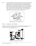
Page 63: ...April 17 2000 Manual Versio n 1 0 B 2 Figure B 2 Typical Cushion Wiring Diagram...
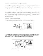
Page 64: ...April 17 2000 Manual Versio n 1 0 B 3 Figure B 3 Conceptual Dual Resolver Mounting...
Page 65: ...April 17 2000 Manual Versio n 1 0 B 4 Figure B 4 Typical AMCI Dual Resolver Wiring Diagram...
Page 66: ...April 17 2000 Manual Versio n 1 0 B 5 Figure B 5 Typical GEMCO Dual Resolver Wiring Diagram...
Page 67: ...April 17 2000 Manual Versio n 1 0 B 6 Figure B 6 Conceptual Linear Transducer Mounting...
Page 68: ...April 17 2000 Manual Versio n 1 0 B 7 Figure B 7 Typical GEMCO Linear Transducer Wiring...
Page 71: ...April 17 2000 Manual Versio n 1 0 B 10...


