April 17, 2000
Man ual Versio n 1.0
5.2
for the shut height setpoint. See section 6 for an explanation of all status messages for the
various sub-systems.
c) Each configured sub-system has a fault message. Under normal conditions, this fault should read
“None”. See section 6 for an explanation of all fault messages for the various sub-systems.
d) Air pressure controlled sub-systems (counterbalances, cushions, and hydraulic overload) display
the current actual pressure for that system in large numbers for easy visibility.
e) Cushions allow the setpoint pressure to be entered directly in psi or to be set in force. This force
can be pounds, kilograms, tons, or metric tons depending on how the system is configured. The
configuration parameters (see section 4.2.1) allow the system to convert from force to psi
automatically.
f) Air pressure controlled sub-systems (counterbalances, cushions, and hydraulic overload) have a
pressure setpoint in psi. This number is the intended pressure for that system.
g) Counterbalances allow the setpoint pressure to be entered directly in psi or to be set in terms of
die weight. This weight can be pounds, kilograms, tons, or metric tons depending on how the
system is configured. The configuration parameters (see section 4.2.1) allow the system to
convert from weight to psi automatically.
h) Slide adjust system show the shut height reported by the transducer in large numbers for easy
visibility. This number will be in inches or millimeters depending on how the system is
configured. See section 4.2.2 for details.
i) The slide setpoint is the desired shut height for a slide in inches or millimeters depending on how
the system is configured (see section 4.2.2 for details).
j) Each configured sub-system has an indicator that tells what mode the system is in - ON, OFF, or
MANUAL. See section 4 for details on the mode.
k) Each configured sub-system is named at the top of the box in which its parameters and settings
are shown.
l) Hydraulic overloads allow the setpoint pressure to be entered directly in psi or to be set in terms
of press trip point. This point can be pounds, kilograms, tons, or metric tons depending on how
the system is configured. The configuration parameters (see section 4.2.1) allow the system to
convert from trip point to psi automatically.
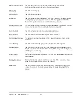
There are a number of softkeys in this screen:
“CHANGE NUMBER”
This key allows the parameter that the editing cursor is currently on to be
changed. The editing cursor may be placed on a parameter using the up,
down, left, and right arrow keys. This key is not always available depending
on the access code configuration as defined in section 2.
Summary of Contents for OmniLink 5000
Page 5: ...April 17 2000 Manual Versio n 1 0 iv...
Page 38: ...April 17 2000 Manual Versio n 1 0 4 14...
Page 63: ...April 17 2000 Manual Versio n 1 0 B 2 Figure B 2 Typical Cushion Wiring Diagram...
Page 64: ...April 17 2000 Manual Versio n 1 0 B 3 Figure B 3 Conceptual Dual Resolver Mounting...
Page 65: ...April 17 2000 Manual Versio n 1 0 B 4 Figure B 4 Typical AMCI Dual Resolver Wiring Diagram...
Page 66: ...April 17 2000 Manual Versio n 1 0 B 5 Figure B 5 Typical GEMCO Dual Resolver Wiring Diagram...
Page 67: ...April 17 2000 Manual Versio n 1 0 B 6 Figure B 6 Conceptual Linear Transducer Mounting...
Page 68: ...April 17 2000 Manual Versio n 1 0 B 7 Figure B 7 Typical GEMCO Linear Transducer Wiring...
Page 71: ...April 17 2000 Manual Versio n 1 0 B 10...

