


April 17, 2000
Man ual Versio n 1.0
6.5
Min Position Reached
The slide has gone as low as the min position programmed in the
configuration menu and will not be allowed to go lower.
Moving Up
The slide is moving up.
Moving Down
The slide is moving down.
System Off
The slide adjust system is turned off. The slide can still be manually moved
by using the jog up and jog down buttons. The slide position will still be
shown if the position transducer is still functioning correctly.
Waiting for Cntr-Bal
The slide adjust system is waiting for the counterbalance, if present, to come
to its correct pressure before automatically moving the slide.
Slide Too High
The slide is higher than the slide setpoint plus tolerance.
Slide Too Low
The slide is lower than the slide setpoint minus tolerance.
Hyd Overload Tripped
The hydraulic overload has tripped. The slide will not move down in this
condition.
Auto-Adjusting
The slide is automatically going to the programmed slide setpoint.
Waiting for Top
The slide must be at the top of the stroke for automatic positioning to occur.
If a job is recalled at the bottom of the stroke, this message will be displayed
until the press is at the top.
E-Stop Button
Emergency stop button is depressed. The slide will not automatically move in
this condition.
Waiting S/A Switch
Waiting for the slide adjust switch to be turned on. The slide cannot move
while the slide adjust switch is in the off position.
LMC is Out
The Link Master Control relay is disengaged for some reason (possibly an
error at the control). No slide movement may be made while the LMC is
tripped.
Summary of Contents for OmniLink 5000
Page 5: ...April 17 2000 Manual Versio n 1 0 iv...
Page 38: ...April 17 2000 Manual Versio n 1 0 4 14...
Page 63: ...April 17 2000 Manual Versio n 1 0 B 2 Figure B 2 Typical Cushion Wiring Diagram...
Page 64: ...April 17 2000 Manual Versio n 1 0 B 3 Figure B 3 Conceptual Dual Resolver Mounting...
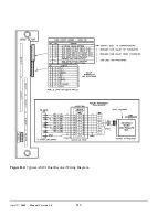
Page 65: ...April 17 2000 Manual Versio n 1 0 B 4 Figure B 4 Typical AMCI Dual Resolver Wiring Diagram...
Page 66: ...April 17 2000 Manual Versio n 1 0 B 5 Figure B 5 Typical GEMCO Dual Resolver Wiring Diagram...
Page 67: ...April 17 2000 Manual Versio n 1 0 B 6 Figure B 6 Conceptual Linear Transducer Mounting...
Page 68: ...April 17 2000 Manual Versio n 1 0 B 7 Figure B 7 Typical GEMCO Linear Transducer Wiring...
Page 71: ...April 17 2000 Manual Versio n 1 0 B 10...