April 17, 2000
Man ual Versio n 1.0
i
Table of Contents
Section 1
Introduction . . . . . . . . . . . . . . . . . . . . . . . . . . . . . . . . . . . . . . . . . . . . . . . . . . . . . . . . . . 1.1
Section 1.1
Counterbalance Control . . . . . . . . . . . . . . . . . . . . . . . . . . . . . . . . . . . . . . . . . . . . . . 1.1
Section 1.2
Cushion Control . . . . . . . . . . . . . . . . . . . . . . . . . . . . . . . . . . . . . . . . . . . . . . . . . . . . 1.1
Section 1.3
Shut Height Control . . . . . . . . . . . . . . . . . . . . . . . . . . . . . . . . . . . . . . . . . . . . . . . . . 1.2
Section 1.4
Hydraulic Overload Control . . . . . . . . . . . . . . . . . . . . . . . . . . . . . . . . . . . . . . . . . . 1.2
Section 2
Parameter Entry and Access Control . . . . . . . . . . . . . . . . . . . . . . . . . . . . . . . . . . . . . . . 2.1
Section 2.1
Parameter Entry . . . . . . . . . . . . . . . . . . . . . . . . . . . . . . . . . . . . . . . . . . . . . . . . . . . . 2.1
Section 2.1.1 Numeric Entries . . . . . . . . . . . . . . . . . . . . . . . . . . . . . . . . . . . . . . . . . . . . . . . . . 2.1
Section 2.1.2 Text Entry . . . . . . . . . . . . . . . . . . . . . . . . . . . . . . . . . . . . . . . . . . . . . . . . . . . . . 2.1
Section 2.2
Access Control . . . . . . . . . . . . . . . . . . . . . . . . . . . . . . . . . . . . . . . . . . . . . . . . . . . . . 2.3
Section 2.2.1 Key Only Mode . . . . . . . . . . . . . . . . . . . . . . . . . . . . . . . . . . . . . . . . . . . . . . . . . . 2.3
Section 2.2.2 Key or Password Mode . . . . . . . . . . . . . . . . . . . . . . . . . . . . . . . . . . . . . . . . . . . . 2.3
Section 2.2.3 Password Only Mode . . . . . . . . . . . . . . . . . . . . . . . . . . . . . . . . . . . . . . . . . . . . . 2.4
Section 2.2.4 Key and Password Mode . . . . . . . . . . . . . . . . . . . . . . . . . . . . . . . . . . . . . . . . . . 2.4
Section 2.2.5 Restricted Items . . . . . . . . . . . . . . . . . . . . . . . . . . . . . . . . . . . . . . . . . . . . . . . . . 2.4
Section 2.2.6 Access Control Operation . . . . . . . . . . . . . . . . . . . . . . . . . . . . . . . . . . . . . . . . . . 2.4
Section 2.2.6.1 RUN/PROG Key Switch Operation . . . . . . . . . . . . . . . . . . . . . . . . . . . . . . 2.4
Section 2.2.6.2 Password System Operation . . . . . . . . . . . . . . . . . . . . . . . . . . . . . . . . . . . 2.5
Section 3.
Installation . . . . . . . . . . . . . . . . . . . . . . . . . . . . . . . . . . . . . . . . . . . . . . . . . . . . . . . . . . . 3.1
Section 3.1
Auto-Setup Module Installation . . . . . . . . . . . . . . . . . . . . . . . . . . . . . . . . . . . . . . . . 3.1
Section 3.2
Valve Systems . . . . . . . . . . . . . . . . . . . . . . . . . . . . . . . . . . . . . . . . . . . . . . . . . . . . . 3.2
Section 3.3
Counterbalance Control Installation . . . . . . . . . . . . . . . . . . . . . . . . . . . . . . . . . . . . 3.3
Section 3.3.1 Counterbalance Pressure Transducer Mounting . . . . . . . . . . . . . . . . . . . . . . . . 3.5
Section 3.3.2 Counterbalance Air Valve System Mounting . . . . . . . . . . . . . . . . . . . . . . . . . . 3.6
Section 3.3.3 Counterbalance System Wiring . . . . . . . . . . . . . . . . . . . . . . . . . . . . . . . . . . . . . 3.6
Section 3.4
Cushion System Installation . . . . . . . . . . . . . . . . . . . . . . . . . . . . . . . . . . . . . . . . . . 3.6
Section 3.4.1 Cushion Pressure Transducer Mounting . . . . . . . . . . . . . . . . . . . . . . . . . . . . . . 3.7
Section 3.4.2 Cushion Air Valve System Mounting . . . . . . . . . . . . . . . . . . . . . . . . . . . . . . . . 3.7
Section 3.4.3 Cushion System Wiring . . . . . . . . . . . . . . . . . . . . . . . . . . . . . . . . . . . . . . . . . . . 3.7
Section 3.5
Hydraulic Overload System Installation . . . . . . . . . . . . . . . . . . . . . . . . . . . . . . . . . 3.8
Section 3.6
Slide Adjust System Installation . . . . . . . . . . . . . . . . . . . . . . . . . . . . . . . . . . . . . . . 3.8
Section 3.6.1 Rotary Transducer Mounting . . . . . . . . . . . . . . . . . . . . . . . . . . . . . . . . . . . . . . . 3.8
Section 3.6.2 Rotary Slide Adjust Wiring . . . . . . . . . . . . . . . . . . . . . . . . . . . . . . . . . . . . . . . . 3.9
Section 3.6.3 Linear Transducer Mounting . . . . . . . . . . . . . . . . . . . . . . . . . . . . . . . . . . . . . . . 3.9
Section 3.6.4 Linear Transducer Slide Adjust Wiring . . . . . . . . . . . . . . . . . . . . . . . . . . . . . . 3.10
Summary of Contents for OmniLink 5000
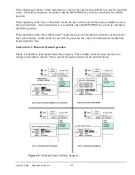
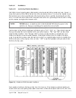
Page 5: ...April 17 2000 Manual Versio n 1 0 iv...
Page 38: ...April 17 2000 Manual Versio n 1 0 4 14...
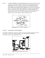
Page 63: ...April 17 2000 Manual Versio n 1 0 B 2 Figure B 2 Typical Cushion Wiring Diagram...
Page 64: ...April 17 2000 Manual Versio n 1 0 B 3 Figure B 3 Conceptual Dual Resolver Mounting...
Page 65: ...April 17 2000 Manual Versio n 1 0 B 4 Figure B 4 Typical AMCI Dual Resolver Wiring Diagram...
Page 66: ...April 17 2000 Manual Versio n 1 0 B 5 Figure B 5 Typical GEMCO Dual Resolver Wiring Diagram...
Page 67: ...April 17 2000 Manual Versio n 1 0 B 6 Figure B 6 Conceptual Linear Transducer Mounting...
Page 68: ...April 17 2000 Manual Versio n 1 0 B 7 Figure B 7 Typical GEMCO Linear Transducer Wiring...
Page 71: ...April 17 2000 Manual Versio n 1 0 B 10...

