background image

April 17, 2000

Man ual Versio n 1.0

A.3

Using the arrow keys, we move the cursor to the “Transducer Type” line.  Looking at table 4.1, we see
that the transducer type for any model pressure transducer with a 250 psi pressure range and a 4 to 20 ma
output is “Type 3”.  We hit the “CHANGE TYPE” softkey and select Type 3 from the list that appears. 
When the proper type is selected, the “Air Pressure” line should change to read the pressure currently in
the cushion system.

Next we move the editing cursor to the “Maximum Pressure” line.  Since we found earlier that the
maximum pressure allowed on the cushion is 90 psi, we hit the “CHANGE MAX PRES” softkey and
key in this value.

Going to the “Minimum Pressure” line, we enter in 2 psi, the value that just supports the weight of the
cushion piston and pressure plate.

Next we have to calculate “Max. Cushion Force”.    We know that for every psi the cushion will
generate 100 pounds of force.  Since the maximum pressure is 90 psi and 2 psi is used to overcome the
cushion weight, the max force will be (90 psi - 2 psi) * 100 square inches - or 8800 pounds.  Note that
units to the right of the number are also an editable parameter.  When the editing cursor is placed on the
Max Die Weight units, we can press the “CHANGE UNIT” softkey to get a list of supported units.  The
units can be pounds, kilograms, tons, or metric tons.  We are using pounds.  Note that the units for
minimum and maximum cushion force will always be the same, but will not necessarily be the same as
the “Display Force As” units.  This allows us to enter the maximum and minimum cushion forces in
whatever units the name plate uses, but operate the press in a different set of units.

“Min. Cushion Force” for the cushion should be 0. This is because the minimum pressure (2 psi) is only
sufficient to balance the cushion itself.

The “Display Force As” units we set to pounds.

The “Fault Time” we leave at 20 seconds.

The “Tolerance” is left at the default 2 psi.

Finally, we go back to the “Mode” line and use the “CHANGE MODE” softkey to toggle the mode to
“ON”.  The “Auto Sets” operation screen can now be used to set the air pressure or cushion force.  See
section 5.2 for operation details.

Section A.3

Example Hydraulic Overload Configuration

This example assumes the hydraulic overload system has been wired to the base auto setup board at
“AS7".  First, some information needs to be gathered.  


From the press manual or the press manufacturer, find the minimum air pressure at which the hydraulic
overload system will reliably operate and the tonnage trip point that corresponds to that pressure.  Also
find the maximum pressure at which the hydraulic overload is intended to operate and the tonnage trip
point that corresponds to that pressure.  Assume we find that the maximum  pressure is 80 psi and
corresponds to a 400 ton trip point.  We also find that the press manufacturer recommends a pressure no
lower than 20 psi which represents a 100 ton trip point.

Summary of Contents for OmniLink 5000

Page 1: ...OmniLink 5000 System 5000 Press Control AUTO SETUP MODULE COLOR DISPLAY OPERATING MANUAL LINK ELECTRIC SAFETY CONTROL COMPANY 444 McNALLY DRIVE NASHVILLE TN 37211 PH 615 833 4168 FAX 615 834 1984...

Page 2: ...peration 2 4 Section 2 2 6 2 Password System Operation 2 5 Section 3 Installation 3 1 Section 3 1 Auto Setup Module Installation 3 1 Section 3 2 Valve Systems 3 2 Section 3 3 Counterbalance Control In...

Page 3: ...and Recall Issues 5 8 Section 6 Diagnostics Fault and Status Messages 6 1 Section 6 1 Main Module Messages 6 1 Section 6 2 Counterbalance Cushion and Hydraulic Overload Fault Messages 6 1 Section 6 3...

Page 4: ...nual Versio n 1 0 iii Appendix F Specifications F 1 Section F 1 5000 10A Pressure Control Board F 1 Section F 2 5000 10B Linear Shut Height Control Board F 1 Section F 3 5000 10C Rotary Shut Height Co...

Page 5: ...April 17 2000 Manual Versio n 1 0 iv...

Page 6: ...d machines by maintaining drive edge gear tooth contact in the press downstroke Decreases the downstroke stopping time of the press since less load is seen by the brake in the downstroke Enhances safe...

Page 7: ...enhancing parts quality and reducing setup time This system uses the existing slide motor starter Section 1 4 Hydraulic Overload Control Most presses use a hydraulic overload system in which an air p...

Page 8: ...the value to be changed It may also simply say CHANGE NUMBER In any case hit this softkey to enter numeric input mode The editing cursor will change to a rectangle around the parameter to be edited c...

Page 9: ...ter at the text cursor In the example above the text cursor is on the T in This and would be replaced with an A The text cursor will automatically move to the right when a letter is selected Note that...

Page 10: ...ed items is prohibited Although the Key Only mode has the advantage of being easy to use it does have a disadvantage This mode cannot give a particular user access to only some of the restricted items...

Page 11: ...and Password Mode The Key and Password mode requires the user to have the RUN PROG key user name and user password Operation is basically the same as the Password only mode except that in addition to...

Page 12: ...o access the restricted items All restricted items are accessible when the RUN PROG key switch is switched to the PROG position When operating in the Key and Password mode the key switch and password...

Page 13: ...play to the Quick Access screen The LOGOUT soft key legend will appear along the bottom of the screen If the operator presses this key he will log out He will no longer have access to the restricted i...

Page 14: ...o the rack to firmly seat the module and tighten the knurled screws The face plate of the ASM is partitioned with labels such as SS1 AS1 etc These labels represent the type of module that can be insta...

Page 15: ...April 17 2000 Manual Versio n 1 0 3 2 or AS4 The plug in terminals on the modules should stick out of the faceplate of the base card...

Page 16: ...pressure re established before the press will stroke Type B An integrated Fill Dump valve with a manual regulator check valve and LOX valve in parallel as shown in Figure 3 3 for cushion but not count...

Page 17: ...s not have to be a minimum pressure This system is ideal for press counterbalance systems as the manual regulator can be set to balance the heaviest die used on the press When the OmniLink 5000 contro...

Page 18: ...Counterbalance with Type C Integrated Valve For automatic control the pressure regulator and check valve are replaced with an air valve system Figures 3 6 and 3 7 illustrate systems using the Type A...

Page 19: ...the counterbalance the transducer tells the system when to stop Because air pressure drops occur across air lines when filling or dumping proper placement of the pressure transducer is very important...

Page 20: ...er to Appendix B Figure B 1 for typical wiring of the counterbalance valve and pressure transducer Note that the auto select connection is used only for a type C valve For type A valves the auto selec...

Page 21: ...rge tank c Right at the outlet on the surge tank that goes to the cushion d Right at the inlet on the surge tank from the Fill Dump valves e If there is no surge tank the pressure transducer should be...

Page 22: ...t be mounted in such a way as to detect slide adjust position and wired to the automatic shut height module Rotary transducers may be used when shafts that turn when shut height is adjusted are access...

Page 23: ...supported Solenoid air valves for air motors are also supported Refer to Appendix B for typical wiring diagrams Figures B 4 and B 5 show the wiring for two supported dual resolvers Figures B 9 and B 1...

Page 24: ...rations Section 3 6 4 Linear Transducer Slide Adjust Wiring A cable must go from the linear transducer mounted on the slide to the auto setup board in the 5000 extended card rack Since the slide goes...

Page 25: ...ns selected for the ASM Section 4 1 Setting up the OmniLink 5000 for the Auto Setup Module The OmniLink 5000 press control must be told that the 5000 10 ASM is installed in the card rack If the module...

Page 26: ...loads are somewhat different but are usually air controlled systems there are some non air controlled hydraulic overloads but the auto setup board does not support them at this time To get to the conf...

Page 27: ...ted by the pressure transducer based on the transducer type selected Note that when the transducer type is changed this pressure will also change even though the actual air pressure stays the same Thi...

Page 28: ...lant air supply is off Also If a type B valve is used Min Pressure must be set above the manual regulator setting For hydraulic overloads the Min Pressure should generally not be set to less than 25 o...

Page 29: ...onfigured Set this parameter to the units that cushion force should be displayed in When the CHANGE UNIT softkey is pressed the choices listed will be pounds lbs kilograms Kgs tons and metric tons Mto...

Page 30: ...nsidered good For instance if tolerance is 2 then a setting of 30 psi will be considered At Pressure from 28 to 32 psi Suggested setting is 2 Transducer Type This value depends on the kind of pressure...

Page 31: ...ain Menu or Press Control screen b With the RUN PROG key switch in the PROG position press the CONFIGURE softkey and enter the configuration code The code is provided separately from this manual for a...

Page 32: ...stem Slide Adjust 1 Slide Adjust 2 Not Configured Stop when the desired name appears This name will appear on the Auto Sets screen Mode Use the CHANGE MODE soft key to cycle the status from ON to MAN...

Page 33: ...the slide adjust system to make a preliminary stop slightly above the desired setpoint The system will then incrementally pulse the slide adjust motor to achieve the desired slide setpoint position T...

Page 34: ...brating the slide adjust module should only be done with no dies installed in the press and for presses equipped with slide counterbalance systems should proceed only after the counterbalance is prope...

Page 35: ...ported slide position may differ from the measured position by as much as 030 Repeat this process with the slide near the bottom of the adjustment range Section 4 2 2 2 Calibrating Rotary Slide Adjust...

Page 36: ...Now the screen should warn that the upper and lower limits must be set correctly before continuing slide calibration See step a above Press the CONTINUE SLIDE CAL softkey to continue the calibration...

Page 37: ...slide configuration g Finally the lower calibration point must be set Use the JOG UP and JOG DOWN softkeys to take the slide near the bottom of the adjustment range The slide should be slightly higher...

Page 38: ...April 17 2000 Manual Versio n 1 0 4 14...

Page 39: ...o Sets screen shows all configured functions and allows their settings to be adjusted Figure 5 1 shows an example Auto Sets screen Note that each configured function slide adjust counterbalance cushio...

Page 40: ...iguration parameters see section 4 2 1 allow the system to convert from weight to psi automatically h Slide adjust system show the shut height reported by the transducer in large numbers for easy visi...

Page 41: ...is on the slide setpoint Note that when an auto adjust sequence is in progress this key will change to CANCEL AUTO ADJUST When pressed under this circumstance it will cancel the auto adjust sequence...

Page 42: ...slide system in the following ways ON Jobs that are recalled will automatically move the slide to the position stored in the job subject to the conditions described in section 5 1 2 The AUTO ADJUST so...

Page 43: ...10 000 and the slide setpoint is 12 000 the auto adjust sequence might take the slide first to 12 015 then back to 12 004 and then pulse the slide the last four thousandths into position This is to e...

Page 44: ...controlled by air pressure and as such are grouped as air systems Each configured air system has its own box on the screen see Figure 5 1 The title of the box has the air system name and the mode the...

Page 45: ...ction 6 for a list of fault messages and their meanings Status The current status of the air system Status messages indicate what the system is doing in the normal course of its operation See section...

Page 46: ...e calculated and displayed Section 5 2 3 Air System Fault and Status The last fault and current status of the air system are displayed for diagnostic and informational purposes Under normal conditions...

Page 47: ...setpoint e When a job is recalled the slide will not complete the auto adjust sequence until the counterbalance system if present has at least reached operating pressure While the slide is waiting it...

Page 48: ...onfig Data The configuration data stored in non volatile ram was corrupted The auto setup card will need to be reconfigured after pressing the reset error key in the Auto Sets screen Bad NV Ram The no...

Page 49: ...n the configuration menu for this system must be reentered Pressure Switch Low There is a pressure switch on the input air supply to the air valves If the input air pressure is too low then the system...

Page 50: ...ve within approximately 2 sec this error will be generated Possible causes are counterbalance pressure so far off that the slide adjust motor cannot overcome it wiring problems starter overloads a pic...

Page 51: ...solver may be mounted too loosely or that the slide adjust motor brake is not holding Resolver Misaligned The fine and coarse resolvers are no longer in proper alignment Indicates that one of the reso...

Page 52: ...nt plus tolerance Slide Too Low The slide is lower than the slide setpoint minus tolerance Hyd Overload Tripped The hydraulic overload has tripped The slide will not move down in this condition Auto A...

Page 53: ...G switch in PROG hit the CONFIGURE softkey After typing the configuration code we press the CONFIGURE AIR softkey Since the counterbalance is wired in at AS1 if the slot reported on the screen in not...

Page 54: ...to be gathered From the press manual or cushion information plate we find that the effective area of the cushion is 100 square inches and the maximum operating pressure is 90 psi This means that the c...

Page 55: ...Note that the units for minimum and maximum cushion force will always be the same but will not necessarily be the same as the Display Force As units This allows us to enter the maximum and minimum cus...

Page 56: ...hen the proper type is selected the Air Pressure line should change to read the pressure currently in the hydraulic overload system Next we use the arrow keys to move the editing cursor to the Maximum...

Page 57: ...of the system The cursor should already be on the Name line so we check to see if the name is already Slide Adjust 1 If not the CHANGE NAME softkey allows us to cycle through the systems During initia...

Page 58: ...sary If desired the Upper Limit and Lower Limit can be set to be more restrictive than the actual minimum and maximum shut heights Next we go to the Mode line of the system and turn it ON by cycling t...

Page 59: ...UN PROG switch in PROG hit the CONFIGURE softkey After typing the configuration code we press the CONFIGURE SLIDE softkey Since the slide adjust system is wired in at SS1 if the slot reported on the s...

Page 60: ...just the limit switch as necessary If desired the Upper Limit and Lower Limit can be set to be more restrictive than the actual minimum and maximum shut heights For rotary transducers the upper and lo...

Page 61: ...et too high What should have happened is that the slide would go over 14 000 come back down to a position just over 14 000 say 14 003 and then pulse into position at 14 000 Since we went under our set...

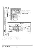
Page 62: ...April 17 2000 Manual Versio n 1 0 B 1 Figure B 1 Typical Counterbalance Wiring Diagram Appendix B Typical Wiring Diagrams...

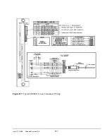
Page 63: ...April 17 2000 Manual Versio n 1 0 B 2 Figure B 2 Typical Cushion Wiring Diagram...

Page 64: ...April 17 2000 Manual Versio n 1 0 B 3 Figure B 3 Conceptual Dual Resolver Mounting...

Page 65: ...April 17 2000 Manual Versio n 1 0 B 4 Figure B 4 Typical AMCI Dual Resolver Wiring Diagram...

Page 66: ...April 17 2000 Manual Versio n 1 0 B 5 Figure B 5 Typical GEMCO Dual Resolver Wiring Diagram...

Page 67: ...April 17 2000 Manual Versio n 1 0 B 6 Figure B 6 Conceptual Linear Transducer Mounting...

Page 68: ...April 17 2000 Manual Versio n 1 0 B 7 Figure B 7 Typical GEMCO Linear Transducer Wiring...

Page 69: ...April 17 2000 Manual Versio n 1 0 B 8 Figure B 8 Typical MTS Temposonics II Linear Transducer Wiring...

Page 70: ...al Versio n 1 0 B 9 Figure B 9 Typical Slide Motor Starter Wiring With Auxiliary Contactor Figure B 10 Typical Slide Motor Starter Wiring Without Auxiliary Contactor Figure B 11 Typical Slide Air Moto...

Page 71: ...April 17 2000 Manual Versio n 1 0 B 10...

Page 72: ...Link 5000 press control Insure that the power to the OmniLink card rack and the OmniLink Operator Interface terminal has been removed 2 Remove the logic board from the card rack 3 Note the location of...

Page 73: ...April 17 2000 Manual Versio n 1 0 C 2...

Page 74: ...2 at the output air port after the check valve When raising the pressure by turning the manual regulator up the pressure forces the check valve open and gauge G1 will be approximately equal to gauge G...

Page 75: ...lve Type C Lockout Procedure When power is removed from the control or if the air system is turned OFF in the configuration menu a type C valve will revert to the manual section and the pressure will...

Page 76: ...__________ Air Pressure Configuration Air Pressure Configuration Slot 2 Board ___________________________ Name ___________________________ Transducer Type __________ Max Pressure __________ Min Press...

Page 77: ..._____ Min Pressure __________ Max Force __________ Min Force __________ Fault Time __________ Tolerance __________ Air Pressure Configuration Air Pressure Configuration Slot 7 Board 0 10 Volt Out Name...

Page 78: ...____ Lower Limit __________ Tolerance __________ Pulse Distance __________ Pulse Time __________ Lock Time __________ Orientation __________ Linear Transducer Slide Configuration Slide Configuration S...

Page 79: ...__ Tolerance __________ Pulse Distance __________ Pulse Time __________ Lock Time __________ Resolver Turns __________ Rotary Transducer Slide Configuration Slide Configuration Slot 2 Board Rotary Tra...

Page 80: ...16ms 5 Amp 75ms Fuse 2 Amp Fast Blow Picofuse Section F 2 5000 10B Linear Shut Height Control Board AC Output Relays Voltage 120VAC Current 1Amp Continuous 20 Amp 16ms 5 Amp 75ms Fuse 2 Amp Fast Blow...

Reviews: