


April 17, 2000
Man ual Versio n 1.0
4.12
NOTE:
It is absolutely critical to set the upper and lower limits correctly before
calibrating a rotary slide adjust system. The calibration process uses this
information to map the turns from the dual resolver into the measurement
space of the slide.
If the upper and lower limits are not set correctly, the
system may fail to calibrate!
NOTE:
It is
very important
to make as accurate a measurement as possible for the
Upper and Lower Calibration Points. If these measurements are wrong, then
the slide position reported by the system will also be wrong!
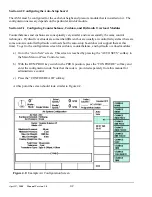
screen of Figure 4.3.
b) Press the “CALIBRATE SLIDE” softkey in the slide configuration screen of Figure 4.3.
c) A screen will appear with a warning that calibrating the slide should not be undertaken without
first reading this manual. Press the “CONTINUE SLIDE CAL.” softkey to continue the
calibration process or “EXIT” to return to slide configuration.
d) Now the screen should warn that the upper and lower limits must be set correctly before
continuing slide calibration. See step “a” above. Press the “CONTINUE SLIDE CAL.” softkey
to continue the calibration process or “EXIT” to return to slide configuration.
e) The number of resolver turns must now be set. Use table 4.3 to find the correct number of turns
for the resolver used in the system.
Table 4.3: Resolver Turns
Manufacturer
Model #
Turns
AMCI
HTT-20-100
100
AMCI
HTT-20-180
180
Patriot (GEMCO)
SD-0410900
64
Patriot (GEMCO)
SD-0410901
128
Press the “CONTINUE SLIDE CAL.” softkey to continue the calibration process or “EXIT” to
return to slide configuration.
f) The system now needs an upper calibration point. With the press as near as possible to bottom
dead center (180 degrees), use the “JOG UP” and “JOG DOWN” softkeys to take the slide near
the top of the adjustment range. The slide should be slightly lower than the upper limit that was
entered on the slide configuration screen. Take the measurement of the shut height in this
position as carefully and accurately as possible and
without moving the slide
enter the number
as requested on the screen.
Summary of Contents for OmniLink 5000
Page 5: ...April 17 2000 Manual Versio n 1 0 iv...
Page 38: ...April 17 2000 Manual Versio n 1 0 4 14...
Page 63: ...April 17 2000 Manual Versio n 1 0 B 2 Figure B 2 Typical Cushion Wiring Diagram...
Page 64: ...April 17 2000 Manual Versio n 1 0 B 3 Figure B 3 Conceptual Dual Resolver Mounting...
Page 65: ...April 17 2000 Manual Versio n 1 0 B 4 Figure B 4 Typical AMCI Dual Resolver Wiring Diagram...
Page 66: ...April 17 2000 Manual Versio n 1 0 B 5 Figure B 5 Typical GEMCO Dual Resolver Wiring Diagram...
Page 67: ...April 17 2000 Manual Versio n 1 0 B 6 Figure B 6 Conceptual Linear Transducer Mounting...
Page 68: ...April 17 2000 Manual Versio n 1 0 B 7 Figure B 7 Typical GEMCO Linear Transducer Wiring...
Page 71: ...April 17 2000 Manual Versio n 1 0 B 10...