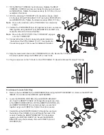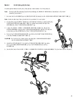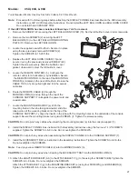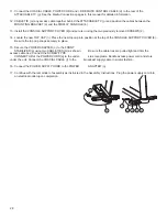
22
FOR 95X ELEVATION INSPIRE UNITS ONLY:
3.
Cable Routing
3a.
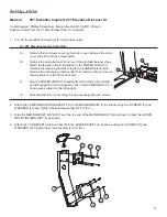
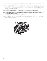
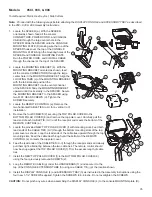
Carefully pull the MEDIA CABLE BUNDLE (12)
(Power and Coaxial)
from inside the CONSOLE BRACKET
(15). Unbundle and straighten the media cables.
3b.
Install the coaxial extension coupler and coaxial extension cable.
3c.
Tape the ends of all CABLES
(Power, Coaxial, I-R Remote Control, Video)
together.
4.
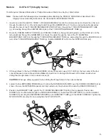
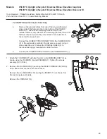
Feed the taped end of the MEDIA CABLES (12) through the large hole in the back of the CONSOLE BRACKET (15).
Carefully pull excess media cable through the CONSOLE BRACKET.
5
Slide one GROMMET (16) over the taped end of the MEDIA CABLES (12).
6.
Hold the MAIN BRACKET ASSEMBLY (5) close to the CONSOLE BRIDGE (13) as shown. With the holes facing
upward, feed the taped end of the MEDIA CABLES (12) through the bottom large hole of the main bracket assembly
and out of the upper hole as shown. Carefully pull excess media cable through the main bracket assembly.
7.
Slide the remaining GROMMET (16) over the taped end of the MEDIA CABLES (12).Install the grommets into
the
access holes.
8.
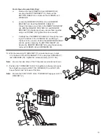
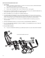
Install the MAIN BRACKET CAPS (19) to the top and bottom of the MAIN BRACKET ASSEMBLY (5).
9.
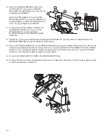
Secure the MAIN BRACKET ASSEMBLY (5) using four SCREWS (17) and WASHERS (18) as shown. Tighten the
screws securely. (8-10 ft. lbs.)
10.
Connect Cables to Console
10a.
Connect the I-R REMOTE CONTROL (A) and VIDEO (B) CABLES to the back of the DISPLAY CONSOLE.
9
19
17
18
16
15
19
95X ELEVATION INSPIRE UNITS ONLY
12
A
B

