16
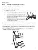
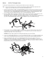
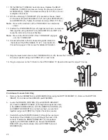
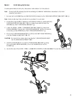
6. Attach the ATTACHABLE TV (k) to the MOUNTING BRACKET (j) using four SCREWS (l), WASHERS (m),
and SHOULDER NYLON WASHERS (n). Tighten the SCREWS to 6-8 in-lbs. Do not overtighten the SCREWS.
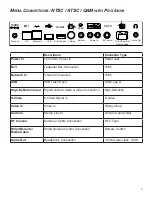
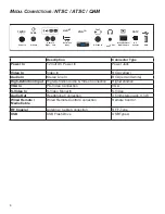
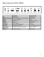
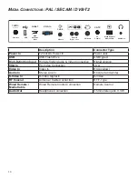
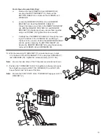
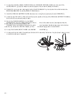
7. Connect the AUDIO / VIDEO / I-R REMOTE CONTROL CABLE (a), POWER SUPPLY CORD (b), and the COAXIAL
CABLE (c), to the rear of the ATTACHABLE TV (k). See the
Media Connections
pages in this manual for detailed
information.
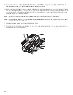
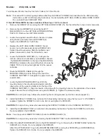
8. Remove the motor shroud and the front cable tie.
9. Mount the POWER ADAPTER (r) inside the open space next to the motor control board using DOUBLE SIDED TAPE.
Connect the SCREW- TYPE CONNECTOR (u) of the POWER ADAPTER to the pre-wired TV POWER CABLE (v).
Bundle excess power cord and store inside the left upright. Connect the POWER SUPPLY CORD (c) to the
POWER ADAPTER (r).
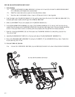
10. Replace the motor shroud using the screws provided.
11.
Connect the COAXIAL CABLE (c) to the broadcast supply in a similar fashion.
Note: Be sure to leave 12” of excess coaxial cable between the fl oor and the coaxial connection on the unit to
accommodate elevation of the unit.
12. Continue with the remainder of assembly as instructed in the
Integrity Series Assembly Instructions
. Plug the POWER
SUPPLY CORD into an electrical outlet upon completion.
k
l
m
n
j
r
u
v
c
s

