Operating Instructions
78
10.4 Maintenance Bypass
The STS2/PDU is equipped with two key-interlocked, bypass breakers, CB4 and CB5, to allow man-
ual bypass of the switch electronics for either input source in the event of switch failure or for mainte-
nance of the switch. Refer to
Figure 3
. While operating on maintenance bypass, all voltages are
removed from the static transfer switch electronics to facilitate safe repair, without de-energizing the
load using a make-before-break switching sequence.
However, the unit can be bypassed using a make-before-break switching sequence only to the same
source to which that the switch is connected, as indicated by the highlighted static transfer switch box
on the Mimic screen.
In the event of source or switch failure, the unit should be bypassed only to the current input source.
For convenience, instructions for the bypass procedure can be displayed on the touch screen by select-
ing the BYP. PROC option from the menu bar.
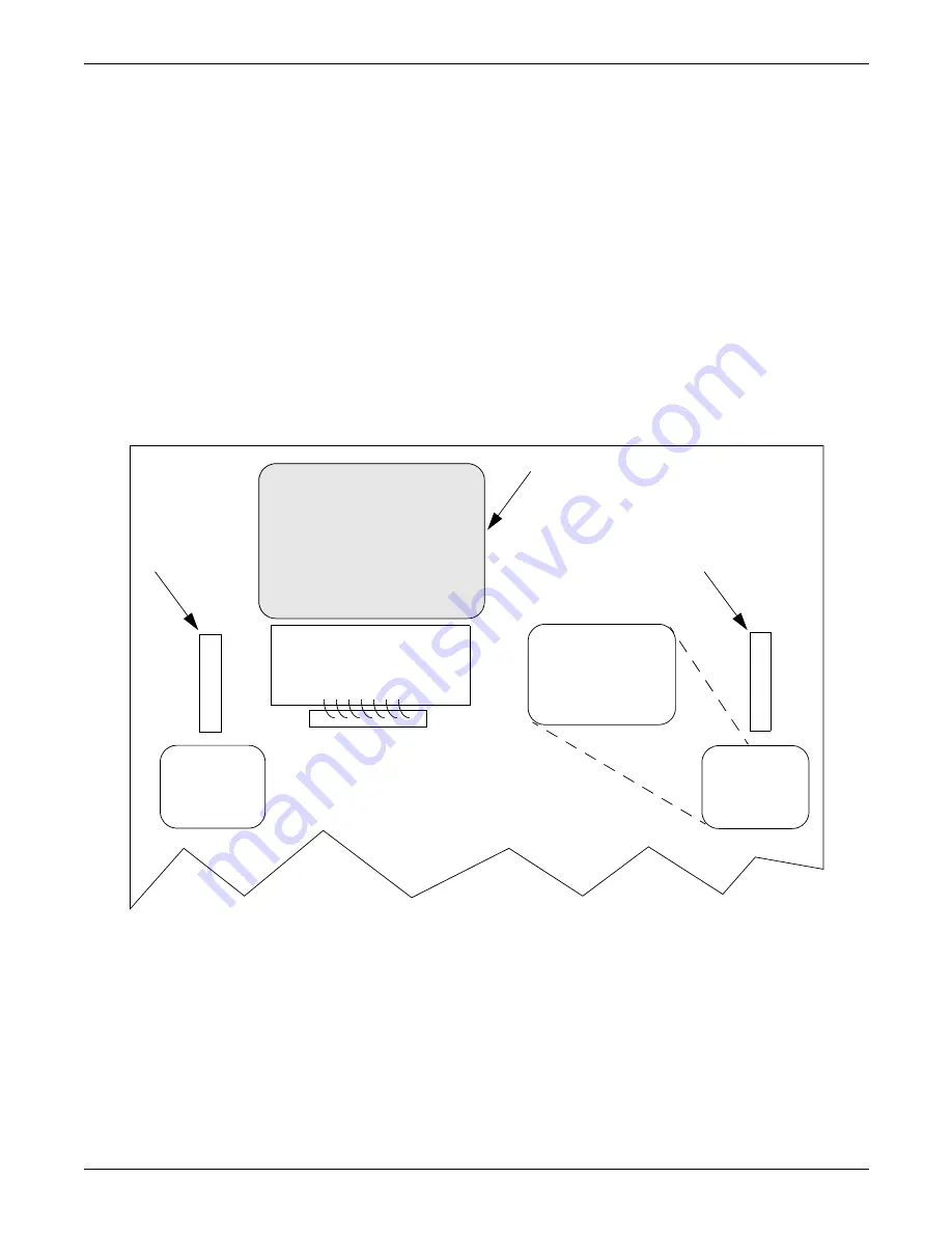
The Mimic is used to verify the status of the unit during the bypass procedures. In the unlikely event
that the Color Graphical Display is not available, open the front door and look through the slots in the
control door. If you can see green LEDs on the gate driver board through that slot, then the unit is
connected to the source referenced on the label below that slot. See
Figure 61
.
Figure 61 Gate board viewing slot locations
Green LEDS on the
Gate Driver Board
are viewable through
this slot indicate that
the STS is on
Source 1
GREEN LEDS ON
THE GATE DRIVER
BOARD ARE VIEW-
ABLE THROUGH
THIS SLOT INDICATE
THAT THE STS IS ON
SOURCE 1
Viewing Slot
for the Source 1
Gate Drive Board
Touch Screen
GREEN LEDS ON
THE GATE DRIVER
BOARD ARE VIEW-
ABLE THROUGH
THIS SLOT INDI-
CATE THAT THE STS
IS ON SOURCE 2
Viewing Slot
for the Source 2
Gate Drive Board
Summary of Contents for PDUTM
Page 25: ...Installation Drawings 17 7 0 INSTALLATION DRAWINGS Figure 7 Outline drawing 250A STS2 PDU ...
Page 42: ...Installation Drawings 34 Figure 24 Electrical field connections 250A STS2 PDU input with CB3 ...
Page 46: ...Installation Drawings 38 Figure 28 Electrical field connections 800A STS2 PDU input with CB3 ...
Page 63: ...Installation Drawings 55 Figure 45 Control wiring 800A STS2 PDU left side distribution ...
Page 64: ...Installation Drawings 56 Figure 46 Control wiring 800A STS2 PDU right side distribution ...
Page 65: ...Installation Drawings 57 Figure 47 Control connection location 250A STS2 PDU ...
Page 66: ...Installation Drawings 58 Figure 48 Control connection location 400 800A STS2 PDU ...
Page 68: ...Installation Drawings 60 Figure 50 Control wiring for the programmable relay board option ...
Page 69: ...Installation Drawings 61 Figure 51 Control wiring for the input contact isolator board option ...
Page 70: ...Installation Drawings 62 Figure 52 Control wiring for comms board ...
Page 71: ...Installation Drawings 63 Figure 53 Control wiring for the internal modem option ...
Page 72: ...Installation Drawings 64 Figure 54 Control wiring for the Network Interface Card NIC option ...
Page 73: ...Installation Drawings 65 Figure 55 Control wiring for the RS 232 Port ...
Page 74: ...Installation Drawings 66 Figure 56 Control wiring for remote source selection option ...
Page 75: ...Installation Drawings 67 Figure 57 Color LCD touch screen display ...
Page 155: ......

