Operating Instructions
80
10.4.2 Bypass Procedures for Source 2
To bypass the switch for Source 2:
1. Verify Source 2 is supplying power via the Mimic.
• If the Color Graphical Display is not available, check the gate driver board LEDs through the
slots in the control panel. See
Figure 61
.
2. Remove the interlock key from CB4 and place it in CB5 interlock.
3. Open the alternate source input breaker CB1.
4. Rotate and remove the interlock key.
5. Insert the key in the CB5 bypass breaker interlock.
6. Rotate interlock keys in the CB5 bypass breaker interlock to retract the interlock.
7. Close bypass breaker CB5.
8. Verify the breaker status on the Mimic screen.
9. Open source input breaker CB2.
10. Rotate the interlock key and remove it to lockout the breaker.
11. Secure the key, per your site’s lockout/tagout procedure.
12. Open output breakers CB3 and CB3A (if supplied) to remove power from static switch.
To return to normal mode:
1. Insert the key in the CB2 breaker interlock.
2. Rotate the key to retract the interlock.
3. Close source input breaker CB2.
4. Verify Source 2 and CB2 breaker status on the Mimic screen.
5. Close output breakers CB3 and CB3A (if supplied).
6. Verify CB3 and CB3A breaker status and STS SOURCE 2 and OUTPUT boxes are highlighted on
the Mimic screen.
7. Open bypass breaker CB5.
8. Rotate the keys in CB5 interlock to extend the interlock.
9. Remove the proper key from CB5 interlock and insert it into CB1 breaker interlock.
10. Rotate the key to retract the CB1 breaker interlock.
11. Close source input breaker CB1.
12. Verify the STS SOURCE 1 box and CB1 breaker status on the Mimic screen.
• If the Color Graphical Display is not available, check the gate driver board LEDs through the
slots in the control panel. See
Figure 61
.
10.5 Normal System Shutdown
The STS2/PDU can be shut down from either the static switch mode or the bypass mode.
10.5.1 Shutdown in Static Transfer Switch Mode
When the STS2/PDU is operating on static transfer switch mode (not maintenance bypass mode):
1. Turn off the load equipment per manufacturer’s recommendations.
2. Open CB8 or panelboard breakers and mains if supplied
3. Open CB3 to turn off the static switch output.
• Open CB3A if the Static Transfer Switch 2 Power Distribution Unit has a redundant output
configuration.
4. Open the input switches CB1 and CB2.
5. To completely de-energize the unit, open CB6 and CB7.
NOTE
If you wish to bypass the Source 2 static transfer switch but Source 1 is presently active, you must first
transfer to Source 2. See
10.2 - Manual Transfer / Preferred Source Selection
.
Summary of Contents for PDUTM
Page 25: ...Installation Drawings 17 7 0 INSTALLATION DRAWINGS Figure 7 Outline drawing 250A STS2 PDU ...
Page 42: ...Installation Drawings 34 Figure 24 Electrical field connections 250A STS2 PDU input with CB3 ...
Page 46: ...Installation Drawings 38 Figure 28 Electrical field connections 800A STS2 PDU input with CB3 ...
Page 63: ...Installation Drawings 55 Figure 45 Control wiring 800A STS2 PDU left side distribution ...
Page 64: ...Installation Drawings 56 Figure 46 Control wiring 800A STS2 PDU right side distribution ...
Page 65: ...Installation Drawings 57 Figure 47 Control connection location 250A STS2 PDU ...
Page 66: ...Installation Drawings 58 Figure 48 Control connection location 400 800A STS2 PDU ...
Page 68: ...Installation Drawings 60 Figure 50 Control wiring for the programmable relay board option ...
Page 69: ...Installation Drawings 61 Figure 51 Control wiring for the input contact isolator board option ...
Page 70: ...Installation Drawings 62 Figure 52 Control wiring for comms board ...
Page 71: ...Installation Drawings 63 Figure 53 Control wiring for the internal modem option ...
Page 72: ...Installation Drawings 64 Figure 54 Control wiring for the Network Interface Card NIC option ...
Page 73: ...Installation Drawings 65 Figure 55 Control wiring for the RS 232 Port ...
Page 74: ...Installation Drawings 66 Figure 56 Control wiring for remote source selection option ...
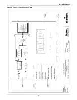
Page 75: ...Installation Drawings 67 Figure 57 Color LCD touch screen display ...
Page 155: ......


