Event Message Help Text
137
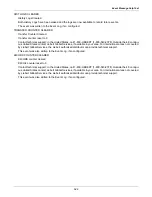
OUTPUT UV
Output Undervoltage
The voltage being supplied to the load has dropped below the acceptable nominal voltage. Check the input
voltage from both sources.
This event and the system status surrounding it have been written to a History Log if the History Logs were not
already full. This event was also written to the Event Log, if so configured.
Press SILENCE on the touch screen to turn off the audible alarm, if so configured. If you are accessing the
STS2/PDU system from a terminal, type
SH
and press RETURN on your keyboard to turn off the audible
alarm.
The alarm has triggered a message to be sent to the modem, if so configured.
If configured to be a latching alarm, press RESET on the display. If you are accessing the unit from a terminal,
type
CA
and press RETURN on your keyboard.
HISTORY LOG FROZEN
History Log Frozen
Both History Logs have been written and no more history logs can be written without clearing one of the logs.
Contact technical support; in the United States, call 1-800-LIEBERT (1-800-543-2378). Outside the 48 contigu-
ous United States contact Liebert Global Services, if available in your area. For international areas not covered
by Liebert Global Services, the Liebert authorized distributor can provide technical support.
Press SILENCE on the touch screen to turn off the audible alarm, if so configured. If you are accessing the
STS2/PDU system from a terminal, type
SH
and press RETURN on your keyboard to turn off the audible
alarm.
This event and the system status surrounding it have been written to a History Log if the History Logs were not
already full. This event was also written to the Event Log, if so configured.
INPUT 1 OVERVOLTAGE
Input 1 Overvoltage
Source 1 is over voltage.
Contact technical support; in the United States, call 1-800-LIEBERT (1-800-543-2378). Outside the 48 contigu-
ous United States contact Liebert Global Services, if available in your area. For international areas not covered
by Liebert Global Services, the Liebert authorized distributor can provide technical support.
Press SILENCE on the touch screen to turn off the audible alarm, if so configured. If you are accessing the
STS2/PDU system from a terminal, type
SH
and press RETURN on your keyboard to turn off the audible
alarm.
This event and the system status surrounding it have been written to a History Log if the History Logs were not
already full. This event was also written to the Event Log, if so configured.
INPUT 1 UNDERVOLTAGE
Input 1 Undervoltage
Source 1 is under voltage.
Contact technical support; in the United States, call 1-800-LIEBERT (1-800-543-2378). Outside the 48 contigu-
ous United States contact Liebert Global Services, if available in your area. For international areas not covered
by Liebert Global Services, the Liebert authorized distributor can provide technical support.
Press SILENCE on the touch screen to turn off the audible alarm, if so configured. If you are accessing the
STS2/PDU system from a terminal, type
SH
and press RETURN on your keyboard to turn off the audible
alarm.
This event and the system status surrounding it have been written to a History Log if the History Logs were not
already full. This event was also written to the Event Log, if so configured.
Summary of Contents for PDUTM
Page 25: ...Installation Drawings 17 7 0 INSTALLATION DRAWINGS Figure 7 Outline drawing 250A STS2 PDU ...
Page 42: ...Installation Drawings 34 Figure 24 Electrical field connections 250A STS2 PDU input with CB3 ...
Page 46: ...Installation Drawings 38 Figure 28 Electrical field connections 800A STS2 PDU input with CB3 ...
Page 63: ...Installation Drawings 55 Figure 45 Control wiring 800A STS2 PDU left side distribution ...
Page 64: ...Installation Drawings 56 Figure 46 Control wiring 800A STS2 PDU right side distribution ...
Page 65: ...Installation Drawings 57 Figure 47 Control connection location 250A STS2 PDU ...
Page 66: ...Installation Drawings 58 Figure 48 Control connection location 400 800A STS2 PDU ...
Page 68: ...Installation Drawings 60 Figure 50 Control wiring for the programmable relay board option ...
Page 69: ...Installation Drawings 61 Figure 51 Control wiring for the input contact isolator board option ...
Page 70: ...Installation Drawings 62 Figure 52 Control wiring for comms board ...
Page 71: ...Installation Drawings 63 Figure 53 Control wiring for the internal modem option ...
Page 72: ...Installation Drawings 64 Figure 54 Control wiring for the Network Interface Card NIC option ...
Page 73: ...Installation Drawings 65 Figure 55 Control wiring for the RS 232 Port ...
Page 74: ...Installation Drawings 66 Figure 56 Control wiring for remote source selection option ...
Page 75: ...Installation Drawings 67 Figure 57 Color LCD touch screen display ...
Page 155: ......


