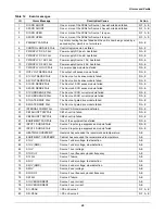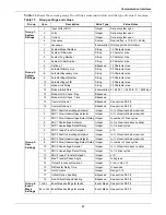
Touch Screen Display
98
13.2.1 Security
Because the STS2/PDU Color Graphical Display provides access to various configuration and moni-
toring choices, a password or key lockout switch may be used to protect access to certain changes,
including:
• Change configuration settings
• Clear logs
• Make a source transfer
• Reset an alarm
Without entering the password or enabling changes with the key lockout switch, you still can:
• View the display, including the mimic, status and event help
• View logs
• View the startup and bypass procedures
• Use the SILENCE button to turn off the audible alarm
Using the Optional Key Lockout Switch
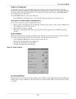
An optional key lockout switch for the STS2/PDU enables or disables the ability to make changes on
the STS2/PDU. The key lockout switch is located on the front of the unit next to the display; it is
behind the front door but can be operated without opening the front door. See
Figures 20
through
22
for location of the key lockout switch.
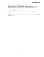
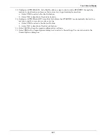
• To disable the changes, turn the key to the top of the switch, toward the closed padlock.
• To enable changes turn the key to the horizontal position, toward the open padlock.
Figure 65 Key lockout switch
Using the Password
If the unit is not equipped with a keylock, a password is required when you attempt to:
• Save changes in the CONFIG menu choices.
• Transfer sources.
• Reset active alarms.
• Clear logs.
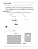
When a password is requested, a keyboard is displayed on the touch screen. After you enter the pass-
word, select OK.
The password is case-sensitive. Password access times out after ten (10) minutes and must be
re-entered to save changes. The time-out period cannot be changed.
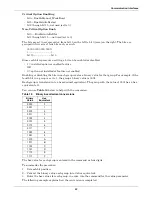
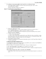
To set or reset the password:
1. Select SYSTEM SETTINGS from the CONFIG menu.
2. Select SYSTEM ID form the SYSTEM SETTINGS menu.
3. Click PASSWORD. A keyboard is displayed.
4. Enter a password. The password must be four (4) alpha-numeric characters and is case sensitive.
5. Click OK.
Changes disabled
Changes enabled
Summary of Contents for PDUTM
Page 25: ...Installation Drawings 17 7 0 INSTALLATION DRAWINGS Figure 7 Outline drawing 250A STS2 PDU ...
Page 42: ...Installation Drawings 34 Figure 24 Electrical field connections 250A STS2 PDU input with CB3 ...
Page 46: ...Installation Drawings 38 Figure 28 Electrical field connections 800A STS2 PDU input with CB3 ...
Page 63: ...Installation Drawings 55 Figure 45 Control wiring 800A STS2 PDU left side distribution ...
Page 64: ...Installation Drawings 56 Figure 46 Control wiring 800A STS2 PDU right side distribution ...
Page 65: ...Installation Drawings 57 Figure 47 Control connection location 250A STS2 PDU ...
Page 66: ...Installation Drawings 58 Figure 48 Control connection location 400 800A STS2 PDU ...
Page 68: ...Installation Drawings 60 Figure 50 Control wiring for the programmable relay board option ...
Page 69: ...Installation Drawings 61 Figure 51 Control wiring for the input contact isolator board option ...
Page 70: ...Installation Drawings 62 Figure 52 Control wiring for comms board ...
Page 71: ...Installation Drawings 63 Figure 53 Control wiring for the internal modem option ...
Page 72: ...Installation Drawings 64 Figure 54 Control wiring for the Network Interface Card NIC option ...
Page 73: ...Installation Drawings 65 Figure 55 Control wiring for the RS 232 Port ...
Page 74: ...Installation Drawings 66 Figure 56 Control wiring for remote source selection option ...
Page 75: ...Installation Drawings 67 Figure 57 Color LCD touch screen display ...
Page 155: ......


