Introduction to STS2/PDU Operations
71
8.2.2 Transfer
Should the preferred source fail or be outside acceptable voltage limits, the STS2/PDU transfers the
input to the alternate source until the problem is rectified in the preferred source. The unit can be set
to automatically transfer the input back to the preferred source or allow the transfer to be done only
manually.
8.2.3 Transfer Inhibit
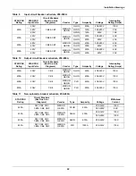
For a transfer to be completed between input sources, the sources must meet certain parameters or
the transfer cannot take place. Uninterrupted transfer between sources is inhibited due to input
source failure, sources out of sync, switch failure or the unit is in bypass mode.
8.2.4 Bypass
The Static Transfer Switch 2 Power Distribution Unit can be manually bypassed to allow the power
from a source to directly flow to the output load. This bypass allows the unit’s electronics to be ser-
viced without dangerous voltages being present.
The STS2/PDU includes key-interlocked maintenance bypass breakers that allow either input
source’s electronics to be bypassed for maintenance without interruption of power to the load. The
maintenance bypass allows all electronics to be isolated from the input, output and bypass connec-
tions. Bypass instructions are available from the touch screen and are discussed later in this manual.
8.3
Operator Controls
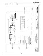
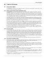
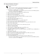
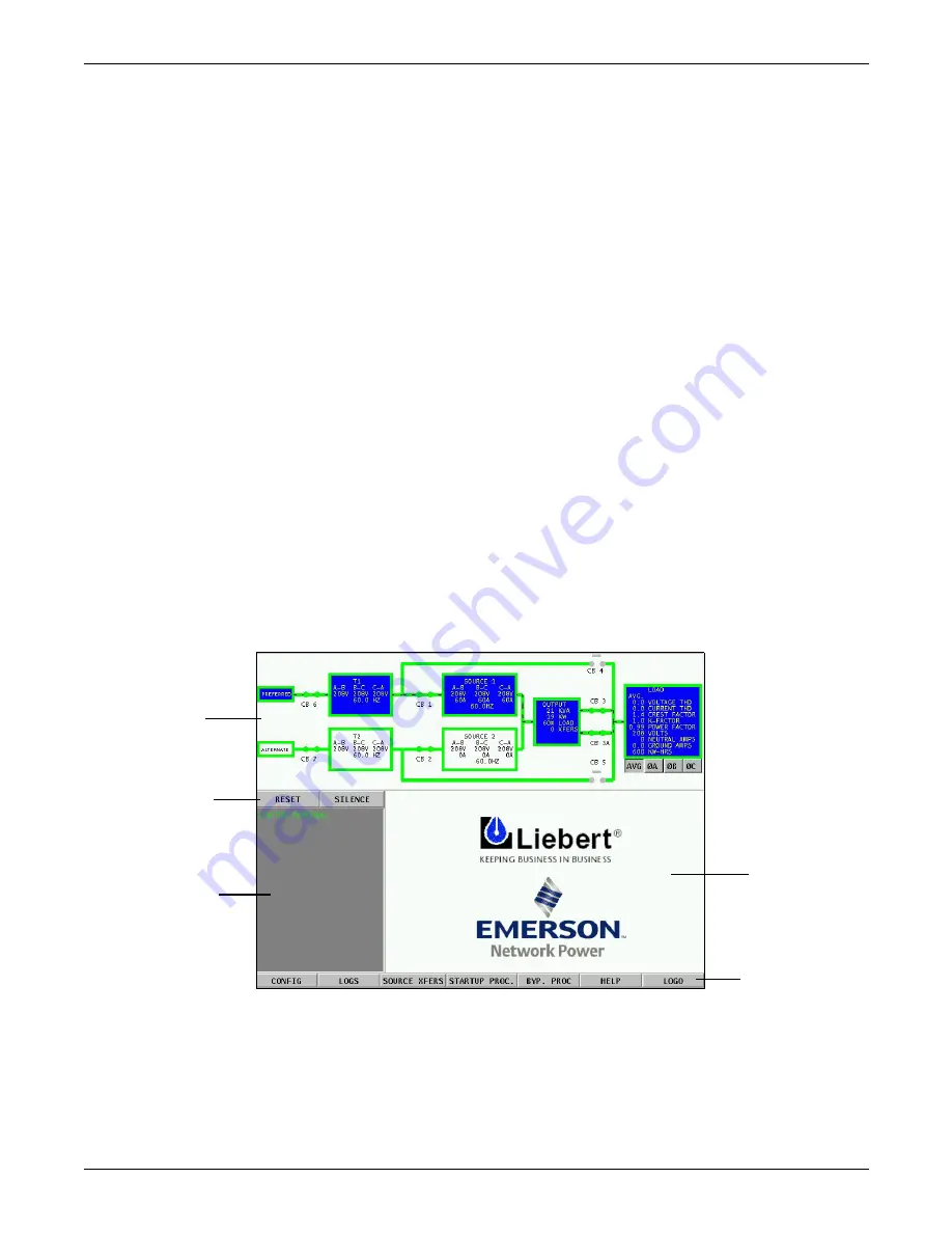
The STS2/PDU is equipped with an interface to configure and monitor the unit either locally or
remotely. The Color Graphical Display is a touch screen LCD that provides a color diagram (Mimic)
that displays the current status of the unit. System parameters are displayed and help is available to
define events. See
Figure 58
below and
Figure 57
in
7.0 - Installation Drawings
. The touch
screen menus allow the operator to initiate source transfers, view event and history logs and view
bypass and other operational instructions.
Figure 58 STS2/PDU touch screen display
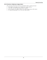
Touch screen control buttons allow you to reset alarms, silence the audible alarm, review configura-
tions, event and history logs, preferred source, startup and bypass procedures and the help menu.
Qualified personnel, with a password, can use these menus to configure parameters, select a pre-
ferred source and do manual source transfers.
Units can be accessed from a terminal or a PC running terminal emulation software attached to the
unit. Through the RS-232 access, you can monitor and configure the unit, plus remotely select a pre-
ferred source. See
12.1 - Using the RS-232 Port
for instructions on using the RS-232 interface.
Mimic
Event display
Event controls
Display panel
and help
screen
Menu options
Summary of Contents for PDUTM
Page 25: ...Installation Drawings 17 7 0 INSTALLATION DRAWINGS Figure 7 Outline drawing 250A STS2 PDU ...
Page 42: ...Installation Drawings 34 Figure 24 Electrical field connections 250A STS2 PDU input with CB3 ...
Page 46: ...Installation Drawings 38 Figure 28 Electrical field connections 800A STS2 PDU input with CB3 ...
Page 63: ...Installation Drawings 55 Figure 45 Control wiring 800A STS2 PDU left side distribution ...
Page 64: ...Installation Drawings 56 Figure 46 Control wiring 800A STS2 PDU right side distribution ...
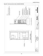
Page 65: ...Installation Drawings 57 Figure 47 Control connection location 250A STS2 PDU ...
Page 66: ...Installation Drawings 58 Figure 48 Control connection location 400 800A STS2 PDU ...
Page 68: ...Installation Drawings 60 Figure 50 Control wiring for the programmable relay board option ...
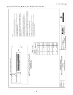
Page 69: ...Installation Drawings 61 Figure 51 Control wiring for the input contact isolator board option ...
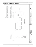
Page 70: ...Installation Drawings 62 Figure 52 Control wiring for comms board ...
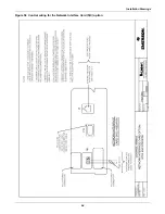
Page 71: ...Installation Drawings 63 Figure 53 Control wiring for the internal modem option ...
Page 72: ...Installation Drawings 64 Figure 54 Control wiring for the Network Interface Card NIC option ...
Page 73: ...Installation Drawings 65 Figure 55 Control wiring for the RS 232 Port ...
Page 74: ...Installation Drawings 66 Figure 56 Control wiring for remote source selection option ...
Page 75: ...Installation Drawings 67 Figure 57 Color LCD touch screen display ...
Page 155: ......


