Operating Instructions
76
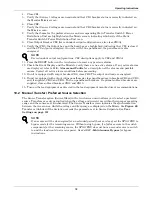
4. Close CB1.
5. Verify that Source 1 voltages are nominal and that CB1 breaker status is correctly indicated on
the Monitor/Mimic screen.
6. Close CB2.
7. Verify that Source 2 voltages are nominal and that CB2 breaker status is correctly indicated on
the Mimic screen.
8. Verify that boxes for the preferred source and corresponding Static Transfer Switch 2 Power
Distribution Unit are highlighted on the Mimic screen, indicating which side of the Static
Transfer Switch 2 Power Distribution Unit is on.
9. Close Output Breaker CB3 (for redundant output configurations, also close CB3A).
10. Verify that CB3, the Output box and the Load box are highlighted, indicating that CB3 is closed
and the STS output is energized. On units with I-line panelboard, the panelboard is also
energized.
11. Press the RESET button on the touch screen to reset any previous alarms.
12. Check the Event Display and the Mimic to verify there are no active alarms. If any active alarms
are displayed, refer to
11.0 - Alarms and Faults
for a description of the alarms and possible
causes. Correct all active alarm conditions before proceeding.
13. If unit is equipped with output breaker CB8, close CB8. The output and load are energized.
14. If unit is equipped with output inline panelboards, close panelboard main breakers CB8 and CB9
and, if supplied, CB10 and CB11. Turn on panelboard breakers. If optional subfeed breakers are
supplied, close subfeed breakers CB12 and CB13.
15. Turn on the load equipment as directed in the load equipment manufacturer’s recommendations.
10.2 Manual Transfer / Preferred Source Selection
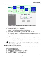
The Source Transfer option (Source Xfers) in the touch screen menu allows you to select a preferred
source. Transfers are only permitted when the voltage and current are within their proper operating
range and the sources are synchronized. The Source Transfer screen indicates the synchronization
between the two sources, while the voltage and frequency are displayed on the Mimic. See
Figure 60
.
Transfer is inhibited if the deviation exceeds the parameter set in Source Setpoints. See
User
Settings on page 101
.
NOTE
For redundant output configurations, CB3 descriptions apply to CB3 and CB3A.
NOTE
If one source will be de-energized for an extended period (hours or days), set the STS2/PDU to
bypass mode for the remaining source. Without using bypass, if a failure occurs in the switch
components for the remaining source, the STS2/PDU does not have a second source to switch
to and the load would not receive power. See
14.2.12 - Maintenance Bypass
for bypass
instructions.
Summary of Contents for PDUTM
Page 25: ...Installation Drawings 17 7 0 INSTALLATION DRAWINGS Figure 7 Outline drawing 250A STS2 PDU ...
Page 42: ...Installation Drawings 34 Figure 24 Electrical field connections 250A STS2 PDU input with CB3 ...
Page 46: ...Installation Drawings 38 Figure 28 Electrical field connections 800A STS2 PDU input with CB3 ...
Page 63: ...Installation Drawings 55 Figure 45 Control wiring 800A STS2 PDU left side distribution ...
Page 64: ...Installation Drawings 56 Figure 46 Control wiring 800A STS2 PDU right side distribution ...
Page 65: ...Installation Drawings 57 Figure 47 Control connection location 250A STS2 PDU ...
Page 66: ...Installation Drawings 58 Figure 48 Control connection location 400 800A STS2 PDU ...
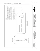
Page 68: ...Installation Drawings 60 Figure 50 Control wiring for the programmable relay board option ...
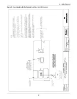
Page 69: ...Installation Drawings 61 Figure 51 Control wiring for the input contact isolator board option ...
Page 70: ...Installation Drawings 62 Figure 52 Control wiring for comms board ...
Page 71: ...Installation Drawings 63 Figure 53 Control wiring for the internal modem option ...
Page 72: ...Installation Drawings 64 Figure 54 Control wiring for the Network Interface Card NIC option ...
Page 73: ...Installation Drawings 65 Figure 55 Control wiring for the RS 232 Port ...
Page 74: ...Installation Drawings 66 Figure 56 Control wiring for remote source selection option ...
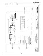
Page 75: ...Installation Drawings 67 Figure 57 Color LCD touch screen display ...
Page 155: ......


