


Connecting to a PBX or ISDN system
If you use a PBX or ISDN converter or terminal adapter, then follow these steps to connect the equipment:
1
Connect one end of the telephone cable that came with the printer to the printer LINE port .
2
Connect the other end of the telephone cable to the port designated for fax and telephone use.
Notes:
•
Make sure the terminal adapter is set to the correct switch type for your region.
•
Depending on the ISDN port assignment, you may have to connect to a specific port.
•
When using a PBX system, make sure the call waiting tone is off.
•
When using a PBX system, dial the outside line prefix before dialing the fax number.
•
For more information on using the fax with a PBX system, see the documentation that came with your PBX
system.
Connecting to a distinctive ring service
A distinctive ring service may be available from your telephone service provider. This service allows you to have multiple
telephone numbers on one telephone line with each telephone number having a different ring pattern. This may be
useful for distinguishing between fax and voice calls. If you subscribe to a distinctive ring service, follow these steps to
connect the equipment:
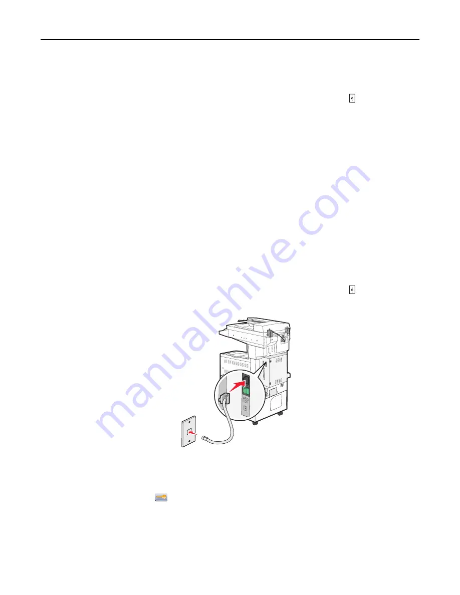
1
Connect one end of the telephone cable that came with the printer to the printer LINE port .
2
Connect the other end of the telephone cable to an active analog telephone wall jack.
3
Change the Distinctive Rings setting to match the setting you want the printer to answer:
Note:
The factory default setting for distinctive rings is
On
. This allows the printer to answer single, double, and
triple ring patterns.
a
On the home screen, touch
.
b
Touch
Settings
.
c
Touch
Fax Settings
.
d
Touch
Analog Fax Settings
.
e
Touch the down arrow until
Distinctive Ring Settings
appears
Faxing
108
Summary of Contents for X860de
Page 6: ...Edition notice 287 Power consumption 291 Index 304 Contents 6 ...
Page 211: ...3 Place the tray into the printer 4 Remove the cable cover Maintaining the printer 211 ...
Page 242: ...231 paper jam 1 Open Door D 2 Remove the jam D D 3 Close Door D Troubleshooting 242 ...
Page 250: ...282 paper jam 1 Open Door F 2 Remove the jam 3 Close Door F Troubleshooting 250 ...
Page 254: ...28x paper jam 284 paper jam 1 Open Door F 2 Remove the jam 3 Close Door F Troubleshooting 254 ...


