


7-62
Service Manual
5062
Go Back
Previous
Next
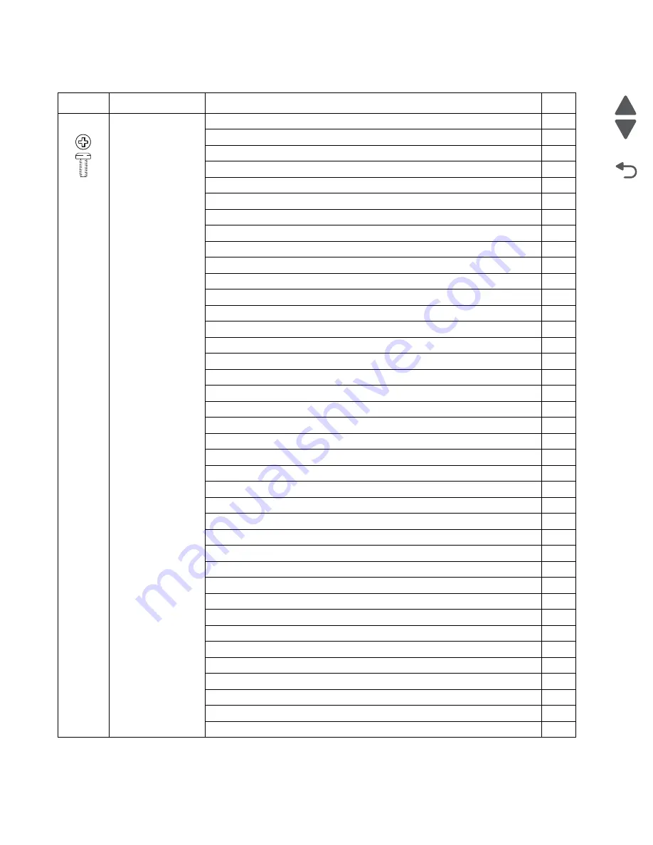
88A0323
Plastite
M3.5 x 8 mm PAN
550-sheet top metal cover to 550-sheet drawer
10
550-sheet bottom cover to 550-sheet drawer
8
550-sheet option deflector to 550-sheet drawer
1
550-sheet drive assembly to 550-sheet drawer
6
ACM bias spring to lower frame
1
Auto-connect harness to frame
7
Bottom plate to frame
7
Contact bracket to HVPS board
3
Cable retainers to frame
4
Cartridge blower assembly to front frame
1
Exit cooling fan duct to frame
3
Front access door beacon cover to waste toner left cover
2
Front access door pivot to top cover
3
Interlock housing assembly
3
ITU block assembly to frame
3
Left cover to top cover and left frame
2
Left frame cable cover
1
Logo panel to top cover
3
Lower left cover to frame
2
LVPS exit duct to frame
2
LVPS to frame
2
Media rails, left and right, to front lower frame
2
MPF breakaway assembly, front
3
MPF breakaway assembly, rear
2
MPF cable cover to lower frame
2
MPF connector cover to duplex assembly
3
MPF drive assembly to frame
3
Operator panel assembly to top cover
2
Operator panel display bracket to OP cover
4
Printhead access cover to top cover
2
Rear cover to top cover and frame
3
Rear upper cover to rear cover
1
Redrive assembly
3
Right cover
6
Speaker to top cover
1
Top cover to left cover and front frame
3
Tray beacon cable plate assembly
4
UICC card to operator panel cover
4
waste toner left cover to frame
8
Screw identification table (continued)
P/N
Screw type
Location
Qty
Summary of Contents for C792 Family
Page 14: ...xiv Service Manual 5062 Go Back Previous Next ...
Page 19: ...Notices and safety information xix 5062 Go Back Previous Next ...
Page 20: ...xx Service Manual 5062 Go Back Previous Next ...
Page 40: ...1 14 Service Manual 5062 Go Back Previous Next ...
Page 212: ...2 172 Service Manual 5062 Go Back Previous Next ...
Page 468: ...4 214 Service Manual 5062 Go Back Previous Next 7 Remove the motor from the bracket ...
Page 490: ...4 236 Service Manual 5062 Go Back Previous Next 4 Flex the sides to remove the roller frame ...
Page 592: ...4 338 Service Manual 5062 Go Back Previous Next ...
Page 594: ...5 2 Service Manual 5062 Go Back Previous Next Connectors System board ...
Page 610: ...5 18 Service Manual 5062 Go Back Previous Next 5 bin mailbox system card ...
Page 612: ...5 20 Service Manual 5062 Go Back Previous Next Finisher Stacker system card HTU system card ...
Page 616: ...6 4 Service Manual 5062 Go Back Previous Next ...
Page 622: ...7 6 Service Manual 5062 Go Back Previous Next Assembly 3 Front 1 2 4 5 6 7 8 3 3 3 3 ...
Page 624: ...7 8 Service Manual 5062 Go Back Previous Next Assembly 3 1 Front continued 1 2 4 5 1 1 1 3 ...
Page 626: ...7 10 Service Manual 5062 Go Back Previous Next Assembly 4 Left 1 2 4 5 6 8 7 3 ...
Page 628: ...7 12 Service Manual 5062 Go Back Previous Next Assembly 4 1 Left continued 1 2 3 4 ...
Page 630: ...7 14 Service Manual 5062 Go Back Previous Next Assembly 5 Rear 1 2 3 6 11 8 9 12 4 7 5 13 10 ...
Page 632: ...7 16 Service Manual 5062 Go Back Previous Next Assembly 6 Optional 550 sheet tray 2 3 1 ...
Page 644: ...7 28 Service Manual 5062 Go Back Previous Next Assembly 11 Finisher stapler assembly 1 2 ...
Page 648: ...7 32 Service Manual 5062 Go Back Previous Next Assembly 13 5 bin mailbox assembly complete 1 ...
Page 654: ...7 38 Service Manual 5062 Go Back Previous Next Assembly 16 HTU complete 1 ...
Page 662: ...7 46 Service Manual 5062 Go Back Previous Next Assembly 20 HTU with hole punch complete 1 ...
Page 682: ...A 2 Service Manual 5062 Go Back Previous Next Print Quality Pages Page 1 total of five ...
Page 684: ...A 4 Service Manual 5062 Go Back Previous Next Print Quality Pages Page 3 total of five ...
Page 704: ...I 14 Service Manual 5062 Go Back Previous Next ...


