Diagnostic aids
3-21
5062
Go Back
Previous
Next
BASE SENSOR TEST
Use the Base Sensor Test to determine that the sensors located inside the printer are operating correctly. The
following sensors can be checked using this test:
Nearly Narrow Media
Input–S1
Fuser Exit
NarrowMedia
K TMC Sensor (black)
M TMC Sensor (magenta)
C TMC Sensor (cyan)
Y TMC Sensor (yellow)
Input–D0
Input–D1
Input–D2
Fuser Bubble
Redrive Bubble
Input–S2
To run the Base Sensor Test.
1.
From the Diagnostics menu, select
BASE SENSOR TEST.
A list of the sensors appears, with the status of each sensor after the sensor name.
2.
Manually toggle the sensors to verify that each sensor switches from open to closed.
DEVICE TESTS
Quick Disk Test
This test performs a non-destructive read/write on one block per track on the disk. The test reads one block on
each track, saves the data, and proceeds to write and read four test patterns to the bytes in the block. If the
block is good, the saved data is written back to the disk.
1.
From the Diagnostics menu, navigate to:
DEVICE TESTS
>
Quick Disk Test
•
The power indicator
blinks
while the test is in progress.
•
Quick Disk Test/Test Passed
appears if the test passes.
•
Quick Disk Test/Test Failed
appears if the test fails.
2.
Press
Stop
(
X
) to return to the Device Tests menu.
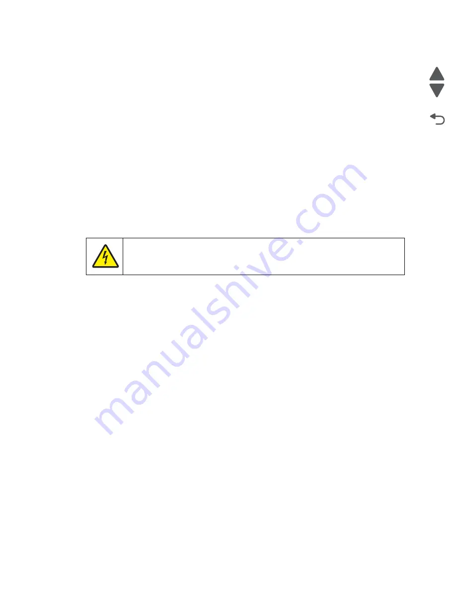
CAUTION
These sensors are near high voltage terminals to the print cartridge. Use a nonconducting
item to toggle these switches and not your hand.
Summary of Contents for C792 Family
Page 14: ...xiv Service Manual 5062 Go Back Previous Next ...
Page 19: ...Notices and safety information xix 5062 Go Back Previous Next ...
Page 20: ...xx Service Manual 5062 Go Back Previous Next ...
Page 40: ...1 14 Service Manual 5062 Go Back Previous Next ...
Page 212: ...2 172 Service Manual 5062 Go Back Previous Next ...
Page 468: ...4 214 Service Manual 5062 Go Back Previous Next 7 Remove the motor from the bracket ...
Page 490: ...4 236 Service Manual 5062 Go Back Previous Next 4 Flex the sides to remove the roller frame ...
Page 592: ...4 338 Service Manual 5062 Go Back Previous Next ...
Page 594: ...5 2 Service Manual 5062 Go Back Previous Next Connectors System board ...
Page 610: ...5 18 Service Manual 5062 Go Back Previous Next 5 bin mailbox system card ...
Page 612: ...5 20 Service Manual 5062 Go Back Previous Next Finisher Stacker system card HTU system card ...
Page 616: ...6 4 Service Manual 5062 Go Back Previous Next ...
Page 622: ...7 6 Service Manual 5062 Go Back Previous Next Assembly 3 Front 1 2 4 5 6 7 8 3 3 3 3 ...
Page 624: ...7 8 Service Manual 5062 Go Back Previous Next Assembly 3 1 Front continued 1 2 4 5 1 1 1 3 ...
Page 626: ...7 10 Service Manual 5062 Go Back Previous Next Assembly 4 Left 1 2 4 5 6 8 7 3 ...
Page 628: ...7 12 Service Manual 5062 Go Back Previous Next Assembly 4 1 Left continued 1 2 3 4 ...
Page 630: ...7 14 Service Manual 5062 Go Back Previous Next Assembly 5 Rear 1 2 3 6 11 8 9 12 4 7 5 13 10 ...
Page 632: ...7 16 Service Manual 5062 Go Back Previous Next Assembly 6 Optional 550 sheet tray 2 3 1 ...
Page 644: ...7 28 Service Manual 5062 Go Back Previous Next Assembly 11 Finisher stapler assembly 1 2 ...
Page 648: ...7 32 Service Manual 5062 Go Back Previous Next Assembly 13 5 bin mailbox assembly complete 1 ...
Page 654: ...7 38 Service Manual 5062 Go Back Previous Next Assembly 16 HTU complete 1 ...
Page 662: ...7 46 Service Manual 5062 Go Back Previous Next Assembly 20 HTU with hole punch complete 1 ...
Page 682: ...A 2 Service Manual 5062 Go Back Previous Next Print Quality Pages Page 1 total of five ...
Page 684: ...A 4 Service Manual 5062 Go Back Previous Next Print Quality Pages Page 3 total of five ...
Page 704: ...I 14 Service Manual 5062 Go Back Previous Next ...


