


4-154
Service Manual
5062
Go Back
Previous
Next
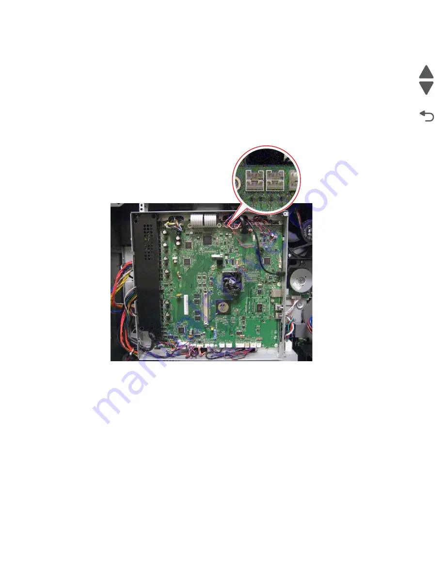
Installation notes:
1.
Install the new system board, and be sure all cables are securely connected. Be sure to reinstall any
toroids you had to remove.
Note:
Some connectors have the same number of pins, so be sure each cable is connected to the correct
connector. For diagrams and tables showing where each cable connects, see
“Locations” on page 5-1
.
Note:
The four cables can be plugged into any of the four connectors (JPK1, JPM1, JPY1, and JPC1) on
the board.
Note:
Pull the four cables into the system board cage area as far as possible so that they would not get
caught in the EP drive motors.
2.
Enter the Diagnostics menu: hold
3
and
6
, turn the printer on, and release the buttons when the splash
screen appears.
3.
Determine if the problem is resolved. Do not perform a normal POR until you are sure you have resolved
the problem.
•
If the problem is
not
resolved, then turn the printer off and reinstall the old part.
•
If the problem is resolved, then turn the printer off and turn it back on without holding any buttons
(
perform a normal POR
).
4.
Verify that the input sources are recognized:
a.
From the Home screen, navigate to:
Menus
>
Paper Menu
>
Paper Size/Type
b.
Make sure all installed options are listed.
5.
Verify that the output options are recognized:
a.
From the Home screen, navigate to:
Menus
>
Paper Menu
>
Bin Setup
>
Output Bin
b.
Make sure all installed options are listed.
Summary of Contents for C792 Family
Page 14: ...xiv Service Manual 5062 Go Back Previous Next ...
Page 19: ...Notices and safety information xix 5062 Go Back Previous Next ...
Page 20: ...xx Service Manual 5062 Go Back Previous Next ...
Page 40: ...1 14 Service Manual 5062 Go Back Previous Next ...
Page 212: ...2 172 Service Manual 5062 Go Back Previous Next ...
Page 468: ...4 214 Service Manual 5062 Go Back Previous Next 7 Remove the motor from the bracket ...
Page 490: ...4 236 Service Manual 5062 Go Back Previous Next 4 Flex the sides to remove the roller frame ...
Page 592: ...4 338 Service Manual 5062 Go Back Previous Next ...
Page 594: ...5 2 Service Manual 5062 Go Back Previous Next Connectors System board ...
Page 610: ...5 18 Service Manual 5062 Go Back Previous Next 5 bin mailbox system card ...
Page 612: ...5 20 Service Manual 5062 Go Back Previous Next Finisher Stacker system card HTU system card ...
Page 616: ...6 4 Service Manual 5062 Go Back Previous Next ...
Page 622: ...7 6 Service Manual 5062 Go Back Previous Next Assembly 3 Front 1 2 4 5 6 7 8 3 3 3 3 ...
Page 624: ...7 8 Service Manual 5062 Go Back Previous Next Assembly 3 1 Front continued 1 2 4 5 1 1 1 3 ...
Page 626: ...7 10 Service Manual 5062 Go Back Previous Next Assembly 4 Left 1 2 4 5 6 8 7 3 ...
Page 628: ...7 12 Service Manual 5062 Go Back Previous Next Assembly 4 1 Left continued 1 2 3 4 ...
Page 630: ...7 14 Service Manual 5062 Go Back Previous Next Assembly 5 Rear 1 2 3 6 11 8 9 12 4 7 5 13 10 ...
Page 632: ...7 16 Service Manual 5062 Go Back Previous Next Assembly 6 Optional 550 sheet tray 2 3 1 ...
Page 644: ...7 28 Service Manual 5062 Go Back Previous Next Assembly 11 Finisher stapler assembly 1 2 ...
Page 648: ...7 32 Service Manual 5062 Go Back Previous Next Assembly 13 5 bin mailbox assembly complete 1 ...
Page 654: ...7 38 Service Manual 5062 Go Back Previous Next Assembly 16 HTU complete 1 ...
Page 662: ...7 46 Service Manual 5062 Go Back Previous Next Assembly 20 HTU with hole punch complete 1 ...
Page 682: ...A 2 Service Manual 5062 Go Back Previous Next Print Quality Pages Page 1 total of five ...
Page 684: ...A 4 Service Manual 5062 Go Back Previous Next Print Quality Pages Page 3 total of five ...
Page 704: ...I 14 Service Manual 5062 Go Back Previous Next ...


