background image

2-58

Service Manual

5026


168.xx—Motor (HCIT elevator) error service check

Step

Questions / actions

Yes

No

1

Is the paper properly loaded in the high-
capacity input tray (HCIT)?

Go to step 2.

Fan the media, and then 
stack flat in the HCIT 
drawer.

2

1. Turn the printer off.
2. Reseat option the HCIT option.
3. Bring the printer up in Diagnostics Menu 

(turn off the printer, press and hold 

 and 

. and turn on the printer). 

4. Select 

PRINT TESTS

, and press 

Select

(

).

5. Select 

HCIT

, and press 

Select

(

).

6. Select 

Single

, and press 

Select

(

).

Did the error clear?

Problem resolved.

Go to step 3.

3

1. Turn the printer off.
2. ,Remove the rear frame cover. See 

“Rear 

frame cover removal” on page 4-33

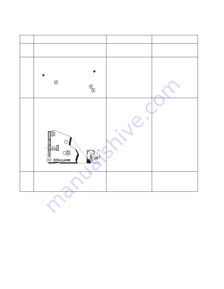
3. Check the option cable in connector 

JOPT1 (A) on the system board for proper 
connection, for cable pinch points, and for 
any other damage to the cable or 
connector

Is the cable damaged?

Replace the option cable. 
See 

“Option cable 

removal” on page 4-111

Go to step 4.

4

Remove the HCIT right cover. See 

“HCIT 

right cover removal” on page 4-167

. Check 

the cable in the HCIT.

Is the cable damaged?

Replace the elevator-up 
cable.

Replace the elevator motor 
with sensor. See 

“HCIT 

elevator motor with 
sensor removal” on 
page 4-171

1

JSB1

JBIN1

JFAN1

JFUSER1

JBOR1

JHVPS1

JMIRR1

JBLW1

JCVR1

JLVPS2

JCARTP1

JCARTS1

JCARTS2

JCARTP2

JDVR1

JTPS1

JOPT1

JFDS1

JINT1

JFDPCK1 JTRAY1 JSEC1

JDX1

JT12

J5

JDIMM1

JOPP1

JT1

JUSB1

JBOOT1

JFMUSB1

J49

JTWF1

JTDBUG1

1

1

1

1

1

1

1

1

1

1

1

1

1

1

1

1

1

1

1

1

1

1

1

1

1

JTLBT1

JPH1

F5

F6

F7

F9

F10

F12

F13

F14

1

1

J10

1

1

A

Summary of Contents for C734 series

Page 1: ...le of contents Start diagnostics Safety and notices Trademarks Index Lexmark and Lexmark with diamond design are trademarks of Lexmark International Inc registered in the United States and or other countries Revised June 8 2009 ...

Page 2: ...ncurring any obligation to you References in this publication to products programs or services do not imply that the manufacturer intends to make these available in all countries in which it operates Any reference to a product program or service is not intended to state or imply that only that product program or service may be used Any functionally equivalent product program or service that does n...

Page 3: ... light description 2 2 Administrative menus 2 3 Power on self test POST sequence 2 4 Symptom tables 2 5 Printer symptom table 2 5 Print quality symptom table 2 5 User status and attendance messages 2 6 Error codes and messages 2 16 Service checks 2 37 110 xx Mirror motor service check 2 37 111 xx 112 xx 113 xx and 114 xx Printhead error service check 2 38 120 xx Fuser error service check 2 39 140 ...

Page 4: ...er Jam service check 2 85 244 27 Paper Jam service check 2 85 244 29 Paper Jam service check 2 85 245 02 Paper Jam service check 2 86 245 03 245 11 Paper Jam service check 2 87 245 05 Paper Jam service check 2 88 245 10 Paper Jam service check 2 89 245 17 Paper Jam service check 2 90 245 29 Paper Jam service check 2 91 900 05 Transfer module error service check 2 91 902 59 Engine software error NV...

Page 5: ...119 Bubble sensor service check 2 120 Dead printer service check 2 122 Exit sensor service check 2 123 Input sensor service check 2 125 Networking service check 2 126 Operator panel service check 2 128 Print quality service check 2 129 Tray linking service check 2 135 Diagnostic aids 3 1 Diagnostics menu 3 2 Diagnostics menu structure 3 2 Available tests 3 2 Registration 3 5 Alignment 3 8 Motor te...

Page 6: ... before maintenance work 4 18 Cover removals 4 19 Front access cover assembly removal 4 19 Left cover removal 4 21 Operator panel assembly removal 4 24 Operator panel bezel removal 4 28 Operator panel buttons removal 4 29 Output bin extension cover removal 4 31 Paper tray dust cover removal 4 32 Rear frame cover removal 4 33 Rear left cover removal 4 34 Rear right cover removal 4 35 Rear upper cov...

Page 7: ...al 4 118 Pick arm roll removal and replacement 4 119 Printer pad removal 4 120 Printhead removal installation and adjustment 4 121 Right bellcrank assembly removal 4 138 System board removal 4 139 System board support shield removal 4 143 Toner level sensor removal 4 146 Top cover camshaft assembly removal 4 148 Transfer module removal 4 154 Transport cable removal 4 156 Transport motor cable remo...

Page 8: ... catalog 7 1 How to use this parts catalog 7 1 Assembly 1 Covers 7 2 Assembly 2 Front 7 4 Assembly 3 Right 7 6 Assembly 4 Rear 7 8 Assembly 5 Left 7 10 Assembly 6 Top 7 12 Assembly 7 Cable parts packet 7 13 Assembly 8 Optional 550 sheet media drawer and tray 7 14 Assembly 9 Optional special media tray assembly 7 15 Assembly 10 Optional high capacity input option HCIT 7 16 Assembly 11 Options and f...

Page 9: ...i ordnungsgemäßer Wartung durch den Kundendienst Laserbestrahlung die Klasse I übersteigen würde Menschen keinesfalls erreicht Avis relatif à l utilisation de laser Pour les Etats Unis cette imprimante est certifiée conforme aux provisions DHHS 21 CFR alinéa J concernant les produits laser de Classe I 1 Pour les autres pays cette imprimante répond aux normes IEC 60825 1 relatives aux produits lase...

Page 10: ...ássio de 5 milliwatts operando numa faixa de comprimento de onda entre 770 e 795 nanómetros O sistema e a impressora laser foram concebidos de forma a nunca existir qualquer possiblidade de acesso humano a radiação laser superior a um nível de Classe I durante a operação normal a manutenção feita pelo utilizador ou condições de assistência prescritas Laserinformatie De printer voldoet aan de eisen...

Page 11: ...taessa olet alttiina näkymättömälle lasersäteilylle Älä katso säteeseen VARNING Osynlig laserstrålning när denna del är öppnad och spärren är urkopplad Betrakta ej strålen Laser notis Denna skrivare är i USA certifierad att motsvara kraven i DHHS 21 CFR underparagraf J för laserprodukter av Klass I 1 I andra länder uppfyller skrivaren kraven för laserprodukter av Klass I enligt kraven i IEC 60825 ...

Page 12: ...825 1 Els productes làser de classe I no es consideren perillosos Aquesta impressora conté un làser de classe IIIb 3b d arseniür de gal li nominalment de 5 mil liwats i funciona a la regió de longitud d ona de 770 795 nanòmetres El sistema làser i la impressora han sigut concebuts de manera que mai hi hagi exposició a la radiació làser per sobre d un nivell de classe I durant una operació normal d...

Page 13: ...Notices and safety information xiii 5026 ...

Page 14: ...xiv Service Manual 5026 ...

Page 15: ...fié Le démontage et l entretien de ce produit pouvant présenter certains risques électriques le personnel d entretien qualifié devra prendre toutes les précautions nécessaires ATTENTION Ce symbole indique la présence d une tension dangereuse dans la partie du produit sur laquelle vous travaillez Débranchez le produit avant de commencer ou faites preuve de vigilance si l exécution de la tâche exige...

Page 16: ... el mantenimiento de este producto está dirigida exclusivamente al personal cualificado de mantenimiento Existe mayor riesgo de descarga eléctrica y de daños personales durante el desmontaje y la reparación de la máquina El personal cualificado debe ser consciente de este peligro y tomar las precauciones necesarias PRECAUCIÓN este símbolo indica que el voltaje de la parte del equipo con la que est...

Page 17: ...oducte està orientada exclusivament a professionals i no està destinada a ningú que no ho sigui El risc de xoc elèctric i de danys personals pot augmentar durant el procés de desmuntatge i de servei d aquest producte El personal professional ha d estar ne assabentat i prendre les mesures convenients PRECAUCIÓ aquest símbol indica que el voltatge de la part de l equip amb la qual esteu treballant é...

Page 18: ...identify the connector locations and test points on the printer 6 Preventive maintenance contains the lubrication specifications and recommendations to prevent problems 7 Parts catalog contains illustrations and part numbers for individual FRUs Appendix A contains service tips and information Appendix B contains representative print samples Conventions Note A note provides additional information W...

Page 19: ...10 Network Lexmark C734dn 5026 230 Duplex and network Lexmark C734dnw 5026 280 Duplex network and wireless Lexmark C736n 5026 410 Network Lexmark C736dn 5026 430 Duplex and network Lexmark CS736dn 5026 439 Duplex and network Standard exit bin Standard exit bin Multipurpose feeder Multipurpose feeder Standard 550 sheet tray tray 1 Standard Optional 550 sheet trays special media 550 sheet tray 1 tra...

Page 20: ...ible with the Lexmark X73x MFP but not with any other Lexmark printers No other options are supported by the C73x The media options include 550 Sheet Drawer This optional input source installs beneath the printer and it holds approximately 550 sheets of 20 lb paper High Capacity Input Tray This optional input source installs beneath the printer and it holds approximately 2000 sheets of 20 lb paper...

Page 21: ... in 450mm 17 7 in 435mm 17 1 in 435mm 17 1 in 435mm 17 1 in 470mm 18 5 in 488mm 19 2 in 527mm 20 7 in 25 7kg 56 7 lbs 25 7kg 56 7 lbs 25 7kg 56 7 lbs Fully configured printer with output paper support extended 525mm 20 7 in 435mm 17 1 in 400mm 15 7 in 25 7 kg 56 7 lbs Fully configured printer with output paper support extended and multipurpose feeder extended 525mm 20 7 in 435mm 17 1 in 584mm 23 0...

Page 22: ...RAM is soldered onto the system board Memory size 256MB Optional memory Optional DIMM Dual Inline Memory Module is a card that can be plugged into an available memory slot on the system board Flash memory is a card that can also be plugged into an available slot Maximum number of memory DIMM slots 1 Maximum number of flash memory slots 1 DIMM memory sizes available 256MB 512MB 1024MB Flash Nand Fl...

Page 23: ...xpansion slots 1 0 1 1 Code Enhancement Socket application solution firmware 1 Hard disk Interface for optional hard disk 1 Environment Specifications Operating Air temperature Operating 15 6 to 32 2 C 60 to 90 F Air temperature Power off 10 to 40 C 50 to 104 F Air Relative Humidity 8 to 80 Wet Bulb Temperature Operating 22 8 C 73 0 F Maximum Web Bulb Temperature Power off 26 7 C 80 1 F Maximum Al...

Page 24: ...ature Power Off 26 7 C 80 1 F Maximum In some cases performance specifications such as paper OCF and EP cartridge usage are specified to be measured at an ambient condition Printing states Lexmark C734n Lexmark C734dn dw Lexmark C736n Lexmark C736dn Typical Electricity Consumption TEC Normal settings 4 61 kwh week 4 69 kwh week Eco Mode settings 3 83 kwh week 4 10 kwh week Average power while prin...

Page 25: ...re made in accordance with ISO 7779 1999 Accoustics Measurement of airborne noise emitted by information technology and telecommunications and reported in conformance with ISO 9296 1988 04 15 Accoustics Declared noise emission values of computer and business equipment Operating mode 1 Meter average bystander sound pressure at 4800 CQ Declared sound power level at 4800 CQ Lexmark C734 C736 Mono pri...

Page 26: ...21 lb Recycled paper less than 75 g m2 20 lb Preprinted papers requiring a high degree of registration Recycled paper less than 80 g m2 21 lb may cause unacceptable results Envelopes All envelopes should be new unused and without package damage Envelopes with excessive curl or twist exceeding 6 mm those stuck together those with bent corners or nicked edges or those that interlock should not be us...

Page 27: ...een engineered to work very well in laser printers despite surface texture Before using these types of paper consult your paper supplier Suitable sheet to sheet coefficient of friction 0 4 0 6 Sufficient bending resistance in the direction of feed Recycled paper paper of lower weight 60 g m2 16 lb bond and or lower caliper 3 8 mils 0 1 mm and paper that is cut grain short for portrait or short edg...

Page 28: ...s 650 650 Optional input sources 550 Sheet Drawer sheets 550 550 High capacity input tray HCIT sheets 2 000 2 000 Specialty Media Drawera sheets 550 or 85 envelopes 550 or 85 envelopes Maximum number of 550 sheet drawers including Speciality Media Drawer 3 4 Maximum number of high capacity input tray must be installed on the bottom 1 1 Maximum number of standard and optional input sources 5 6 Maxi...

Page 29: ... Legal 8 5 x 14 in 3 x 51 4 x 51 Statement 5 5 x 8 5 in Executive 7 25 x 10 5 in Folio 8 5 x 13 in Universalb width x Length 76 2 x 123 8 mm 3 x 4 9 in to 215 9 8 5 x 14 in 148 x 210 mm 5 8 x 8 3 in to 215 8 x 355 6 mm 8 5 x 48 in 76 2 x 123 8 mm 3 x 4 9 in to 215 9 x 1219 mm 8 5 x 48 in c a These sizes are accessible using Universal Size setting b Lower feed reliability may be encountered when fe...

Page 30: ...4 13 x 9 5 in 11 Envelope 4 5 x 10 4 ind 12 Envelope 4 8 x 11 ind a These sizes are accessible using Universal Size setting b Lower feed reliability may be encountered when feeding non standard size media c The maximum length supported by the Lexmark C734 is 914 4mm 36 in d These sizes are accessible using Other Envelope setting Media Sizes continued Primary 550 sheet tray Multipurpose feeder Opti...

Page 31: ... points produces the best print quality Moisture content The amount of moisture in paper affects both print quality and the ability of the printer to feed the paper correctly Leave paper in its original wrapper until it is time to use it This limits the exposure of paper to moisture changes that can degrade its performance Condition paper before printing by storing it in its original wrapper in th...

Page 32: ...mal papers Rough edged rough or heavily textured surface papers or curled papers Recycled papers that fail EN12281 2002 European Paper weighing less than 60 g m2 16 lb Multiple part forms or documents Selecting paper Using appropriate paper prevents jams and helps ensure trouble free printing To help avoid jams and poor print quality Always use new undamaged paper Before loading paper know the rec...

Page 33: ...etic 2 Phillips screwdriver magnetic short blade 7 32 inch 5 5 mm open end wrench 7 0 mm nut driver Needlenose pliers Diagonal side cutters Spring hook Feeler gauges Analog or digital multimeter Parallel wrap plug 1319128 Twinax serial debug cable 1381963 Coax serial debug cable 1381964 Flash light optional Acronyms Delete any unused terms and add any terms that appear in your book BLDC Brushless ...

Page 34: ...andom Access Memory PC Photoconductor pel Picture element pixel POR Power On Reset POST Power On Self Test RIP Raster Imaging Processor SDRAM Synchronous Dual Random Access Memory V ac Volts alternating current V dc Volts direct current Y Yellow ...

Page 35: ... YY In most cases five digits are shown Paper jam messages 2xx xx User attendance messages that indicate a paper jam have been included with the service error codes since repeated instances may indicate an underlying service issue Go to 2xx paper jam messages on page 2 18 User status and attendance messages User status messages provide the user with information on the current status of the printer...

Page 36: ... menu item values or to scroll between screens and menu values Each press moves one item in the list or a different setting for a menu item Press these buttons to scroll items that wrap off of the screen For menu items with numeric values such as Copies press and hold this button to scroll through the values Release the button when the needed number appears Indicator light The two toned light emit...

Page 37: ...ge Substitute Size Network x Setup Page Quality Menu Black Cartridge Paper Texture Wireless Setup Page Utilities Menu Cyan PC Unit Paper Weight Profiles List XPS Menu Magenta PC Unit Paper Loading NetWare Setup Page PDF Menu Yellow PC Unit Custom Types Print Fonts PostScript Menu Black PC Unit Universal Setup Print Directory PCL Emul Menu Waste Toner Box Print Demo PPDS Menu Fuser Asset Report HTM...

Page 38: ...ystem information For example 9 The fuser heater turns on The fuser takes longer to warm up from a cold start than a warm start 10 The operator panel LED starts blinking 11 A clock face appears on the display The following errors or messages may appear Close Door or Insert Cartridge display if the upper front cover is open or the print cartridge is missing Any cartridge errors such as Defective Ca...

Page 39: ...d in place Symptom Action Background Go to Print quality background on page 2 130 Blank page Go to Print quality blank page on page 2 131 Blurred or fuzzy print Go to Print quality blurred or fuzzy print on page 2 132 Half color page Go to Print quality half color page on page 2 132 Horizontal banding Go to Print quality horizontal banding on page 2 132 Horizontal line Go to Print quality horizont...

Page 40: ... parking is enabled and the job meets all the requirements for allowing the job to be parted the printer adds this message Load source size Load paper in the indicated source and of the indicated size and select Continue Additional messages may include Show Me the printer will present instructions Cancel Job the printer job can be cancelled Wait for supplies If job parking is enabled and the job m...

Page 41: ...tore Held Jobs Go Stop If the printer detects Print and Hold or parked jobs stored on the hard disk during Power On Self Test POST Choices are Restore Print jobs are restored and Restoring Held Jobs x y where x is the number of the job restored and y is the total number of jobs to restore You can quit restoring and the remainder of the jobs will remain on the disk but cannot be accessed until they...

Page 42: ...the cable if not connected properly Replace the cable if damaged If the problem still exists replace the system board See System board removal on page 4 139 34 Short Paper Select Continue to clear the message and continue printing Note The printer does not automatically reprint the page that prompted the message Check the tray length and width guides to ensure the media is properly fitted Make sur...

Page 43: ...insufficient memory to perform the Flash Memory Defragment operation The user can Delete font macros and other data in memory Install additional printer memory 38 Memory Full The following options are available Select Continue to clear the message and continue printing The job may not print correctly Cancel the current job Install additional printer memory If this does not fix the problem replace ...

Page 44: ...not fix the problem replace the system board See System board removal on page 4 139 56 Standard Parallel Port Disabled Select Continue to clear the message The printer discards any data received through the parallel port Make sure the Parallel Buffer menu item is not set to Disabled If this does not fix the problem replace the PCI card 56 Parallel Port x Disabled Select Continue to clear the messa...

Page 45: ...ns that require a hard disk If this does not fix the problem replace the system board See System board removal on page 4 139 62 Disk full Select Continue to clear the message and continue processing Any information not previously stored on the hard disk is deleted Delete fonts macros and other data stored on the hard disk Install a larger hard disk If this does not fix the problem replace the syst...

Page 46: ...me cover See Rear frame cover removal on page 4 33 Check the cable in connector JFUSER1 A for proper connection to the system board the cable for pinch points and the cable or the connector for any other damage If the connector is damaged on system board replace the system board See System board removal on page 4 139 If the fuser cable is damaged replace the cable Check for the following continuit...

Page 47: ...age 4 139 82 41 If you continuously get this error then the problem is the aligner motor error Go to 147 xx 920 01 Aligner motor error service check on page 2 50 83 xx Transfer Module Life Warning Select Continue to clear the message and continue printing Order a replacement transfer module When print quality is reduced install the new transfer module using the instruction sheet that comes with th...

Page 48: ...e a screwdriver to ease the camshaft follower back into the groove You need to press down to snap it into position Check the high voltage contacts path especially the finger on the specified photoconductor unit printer is shown with components removed for clarity If the contacts are good replace the HVPS See High voltage power supply HVPS removal on page 4 94 If the problem persists replace the sy...

Page 49: ...Me View Supplies and Tell Me More displays additional information Replace the specified toner cartridge Select Continue to clear the message and continue printing If the problem persists replace the system board See System board removal on page 4 139 88 xx Replace color Cartridge Show Me View Supplies and Tell Me More displays additional information Replace the specified toner cartridge Select Con...

Page 50: ...112 xx 113 xx and 114 xx Printhead error service check on page 2 38 120 00 120 21 Fuser Error An error has occurred in the fuser Remove and reseat the fuser See Fuser removal on page 4 90 POR the printer If the error message persists go to 120 xx Fuser error service check on page 2 39 140 01 140 10 Autocomp Motor Error Tray 1 motor has failed POR the printer If the error message persists go to 140...

Page 51: ...e 2 54 161 01 161 06 Motor Error Tray 2 feed motor failed POR the printer If the error message persists go to 160 xx 161 xx Motor Error option tray 2 service check on page 2 54 162 01 162 06 Motor Error Tray 3 pick motor failed POR the printer If the error message persists go to 162 xx 163 xx Motor Error option tray 3 service check on page 2 55 163 01 163 06 Motor Error Tray 3 feed motor failed PO...

Page 52: ...ia restraints in the paper tray 5 Check the pick arm rolls tires and replace if worn If the problem persists go to 200 11 250 03 Paper Jam error service check on page 2 59 200 17 Input sensor is made when printer powers up or covers are closed Possible causes Paper jam leaving page over sensor Defective input sensor Faulty system board Clear away anything in the paper path that might cause the pap...

Page 53: ...nnection Faulty fuser Faulty system board 1 Clear away anything in the paper path that might cause the paper to jam 2 Ensure proper media is set for the type of paper used 3 Fan media and stack flat in the tray 4 Properly set media restraints in the paper tray If the problem persists go to Bubble sensor service check on page 2 120 201 06 Paper is jammed between the input sensor and the exit sensor...

Page 54: ...per path that might cause the paper to jam If the problem persists go to Bubble sensor service check on page 2 120 201 21 Cartridge motor 1 top or cartridge motor 2 middle has stalled Possible causes Faulty cable connector Faulty cartridge motor Faulty system board Check for anything in the paper path that might cause the paper to jam If clearing a paper jam does not fix the problem go to 143 xx M...

Page 55: ...g properly Go to Exit sensor service check on page 2 123 202 17 Exit sensor is made when the printer powers up or covers are closed Possible causes Damaged paper exit sensor or paper exit sensor flag Damaged fuser autoconnect Faulty fuser DC cable connection Faulty fuser Faulty system board Check for anything in the paper path that might cause the paper to jam The fuser exit sensor may not be func...

Page 56: ...erly Go to Exit sensor service check on page 2 123 The duplex motor may not be functioning properly Go to 146 xx 148 xx Motor MPF duplex error service check on page 2 48 203 20 During duplex the page made the input sensor before the previous page cleared the bubble sensor Possible causes Defective input sensor Faulty system board Check for anything in the duplex paper path that might cause the pap...

Page 57: ...ack it flat in the tray or multipurpose feeder 3 Properly set media restraints in paper tray 4 Check the pick arm rolls tires and replace if worn If the problem persists go to 140 xx 920 02 Autocomp tray 1 motor error service check on page 2 43 241 21 Tray 1 motor stalled Possible causes Incorrect paper loading Paper pick mechanism failure System board failure 1 Remove all media present in the pap...

Page 58: ... media is set for the type of paper used in tray 2 2 Fan media and then stack flat in tray 2 3 Properly set the media restraints in tray 2 Go to 242 03 242 11 Paper Jam service check on page 2 69 242 17 Tray 2 detected a jam from idle Possible causes Paper jam leaving page over sensor Defective input sensor Faulty system board Clear away anything in the paper path that might cause the paper to jam...

Page 59: ...ay 3 paper pick mechanism failure Loading card stock from the special media tray above the fill line 1 Ensure proper media is set for the type of paper used in tray 3 2 Fan media and stack flat in tray 3 3 Properly set the media restraints in tray 3 4 Check the pick arm rolls tires in tray 3 and replace if worn If the previous actions do not fix the problem go to 243 05 Paper Jam service check on ...

Page 60: ...er tray 3 assembly failure Clear away anything in the paper path that might cause the paper to jam Reseat option tray 3 If the problem persists go to 243 27 Paper Jam service check on page 2 79 243 29 Tray 3 is not ready while printing Possible cause is paper tray 3 assembly failure Make sure that tray 3 is correctly inserted If the problem persists go to 243 29 Paper Jam service check on page 2 7...

Page 61: ...e proper media is set for the type of paper used in tray 4 Fan media and then stack flat in tray 4 Properly set the media restraints in tray 4 If the problem persists go to 244 03 244 11 Paper Jam service check on page 2 81 244 17 Tray 4 detected a jam from idle Possible causes Paper jam leaving page over the sensor defective input sensor Faulty system board Clear away anything in the paper path t...

Page 62: ...ism Loading card stock from the special media tray above the fill line 1 Ensure proper media is set for the type of paper used in tray 5 2 Fan media and stack flat in tray 5 3 Properly set the media restraints in tray 5 4 Check the pick arm rolls tires in tray 5 and replace if worn If the problem persists go to 245 05 Paper Jam service check on page 2 88 245 10 Tray 5 page exits pass thru sensor b...

Page 63: ... the problem persists to 200 11 250 03 Paper Jam error service check on page 2 59 250 05 While feeding from the multipurpose feeder the input sensor is not made Possible causes Incorrect media setting Incorrect paper loading Incorrect media restraint setting Multipurpose feeder pick mechanism failure System board failure 1 Remove all the media present in the paper path 2 Ensure proper media is set...

Page 64: ...rors POR the printer If the error message persists replace the system board See System board removal on page 4 139 904 01 904 04 Software Error Unrecoverable system software errors POR the printer If the error message persists replace the system board See System board removal on page 4 139 905 00 905 99 Software Error Unrecoverable system software errors POR the printer If the error message persis...

Page 65: ...POST Error Three toner sensors are not connected POR the printer If the error message persists go to 920 10 POST power on self test Three toner sensors not connected error service check on page 2 99 920 11 POST Error Two toner sensors are not connected POR the printer If the error message persists go to 920 11 POST power on self test Two toner sensors not connected error service check on page 2 10...

Page 66: ...error service check on page 2 104 920 21 POST Error 24 V power supply failure POR the printer If the error message persists replace the low voltage power supply See Low voltage power supply LVPS removal on page 4 98 920 22 POST Error Fuser bubble sensor is not connected If the error message persists go to Bubble sensor service check on page 2 120 920 23 POST Error Duplex motor is not connected POR...

Page 67: ...alled POR the printer If the error message persists go to 925 02 925 04 925 06 Cartridge cooling fan error service check on page 2 113 925 05 Fan Error Fan has stalled POR the printer If the error message persists go to 925 01 925 03 925 05 Fan error service check on page 2 112 925 06 Blower Error Blower has stalled POR the printer If the error message persists go to 925 02 925 04 925 06 Cartridge...

Page 68: ...he system board See System board removal on page 4 139 952 01 952 99 NVRAM Error CRC error has occurred This is recoverable Perform a POR to clear the error 953 01 953 99 NVRAM Failure Operator panel assembly NVRAM failure POR the printer Replace the operator panel assembly if the error message persists See Operator panel assembly removal on page 4 24 954 01 954 99 NVRAM Failure System NVRAM failu...

Page 69: ...e System board removal on page 4 139 964 00 964 88 Emulation Error Download emulation CRC error POR the printer If the error message persists download code a second time 975 00 975 99 Network Error Unrecognized network port Contact your next level of support 976 00 976 99 Network Error Unrecoverable software error in network port Contact your next level of support 978 00 978 99 Network Error Bad c...

Page 70: ...ce the system board See System board removal on page 4 139 990 00 990 29 Option Error Contact your next level of support 991 00 991 29 device Error Specified device has detected an error POR the printer If the error message persists replace the system board See System board removal on page 4 139 1565 Emul Error Load Emul Option In IRs The DLE version contained in the firmware card will not functio...

Page 71: ...re the resistance across fuse F6 A on the system board Is the fuse blown Replace the system board See System board removal on page 4 139 Go to step 4 CAUTION POTENTIAL EYE INJURY Laser Radiation Avoid eye exposure to the beam Always point the printhead laser down into the packaging as shown The laser can cause damage to your eyesight or the eyesight of others 1 JSB1 JBIN1 JFAN1 JFUSER1 JBOR1 JHVPS...

Page 72: ...tment on page 4 121 Go to step 2 2 Turn the printer off and then remove the rear frame cover See Rear frame cover removal on page 4 33 Check the cable in connector JPH1 A 5 V interlock switch cable for proper connection to the system board the cable for pinch points and the cable or connector for any other damage Is the cable damaged Replace the 5 V interlock switch See 5 V interlock switch cable ...

Page 73: ...e the system board See System board removal on page 4 139 Step Questions actions Yes No 1 Check the input voltage switch on the back of the low voltage power supply LVPS Note Some LVPS FRU do not have switches and switch automatically If your does not have a switch go to step 2 Is the voltage level 115 V 230 V properly set Go to step 2 Set the switch for the proper country voltage Step Questions a...

Page 74: ...e fuser See Fuser removal on page 4 90 Does the error clear Problem resolved Go to step 4 4 Turn the printer off and then remove the fuser Check the camshaft follower on the right side If the camshaft follower A is above the crescent shaped groove it needs to be pressed down into the proper location Is the camshaft follower on the right side properly placed in the grove Go to step 5 Press the cams...

Page 75: ...stions actions Yes No 1 JSB1 JBIN1 JFAN1 JFUSER1 JBOR1 JHVPS1 JMIRR1 JBLW1 JCVR1 JCVR1 JLVPS2 JCARTP1 JCARTS1 JCARTS2 JCARTP2 JDVR1 JTPS1 JOPT1 JFDS1 JINT1 JFDPCK1 JTRAY1 JSEC1 JDX1 JT12 J5 JDIMM1 JOPP1 JT1 JUSB1 JBOOT1 JFMUSB1 J49 JTWF1 JTDBUG1 1 1 1 1 1 1 1 1 1 1 1 1 1 1 1 1 1 1 1 1 1 1 1 1 1 JTLBT1 JPH1 F5 F6 F7 F9 F10 F12 F13 F14 1 1 J10 1 1 A 1 JSB1 JBIN1 JFAN1 JFUSER1 JBOR1 JHVPS1 JMIRR1 JBL...

Page 76: ...9 Check for continuity between the following pins of the AC autoconnect and the pins of the connector that connects to the LVPS Is continuity present Replace the system board See System board removal on page 4 139 Replace the fuser AC cable See Fuser AC cable removal on page 4 91 Step Questions actions Yes No DC auto connect JFUSER1 Pin 9 Pin 9 Pin 10 Pin 10 10 9 LVPS connect AC Auto connect Pin 1...

Page 77: ...INT TESTS and press Select 4 Select Tray 1 and press Select 5 Select Single and press Select Does the new pick motor turn before the feed error occurred Replace the paper pick mechanism See Paper pick mechanism assembly removal on page 4 113 Replace the system board See System board removal on page 4 139 1 JSB1 JBIN1 JFAN1 JFUSER1 JFUSER1 JBOR1 JHVPS1 JMIRR1 JBLW1 JCVR1 JLVPS2 JCARTP1 JCARTS1 JCAR...

Page 78: ...dge motor 1 fuser cable removal on page 4 51 Go to step 3 3 Measure the resistance across fuse F6 A on the system board Is the fuser blown Replace the system board See System board removal on page 4 139 Replace the EP drive assembly See Electrophotographic EP drive assembly removal on page 4 69 1 JSB1 JSB1 JBIN1 JFAN1 JFUSER1 JFUSER1 JBOR1 JHVPS1 JMIRR1 JMIRR1 JBLW1 JCVR1 JLVPS2 JCARTP1 JCARTS1 JC...

Page 79: ...rtridge motor 1 fuser motor cable See Cartridge motor 1 fuser cable removal on page 4 51 Go to step 3 3 Measure the resistance across fuse F7 on the system board Is the fuse blown Replace the system board See System board removal on page 4 139 Replace the EP drive assembly See Electrophotographic EP drive assembly removal on page 4 69 1 JSB1 JBIN1 JFAN1 JFUSER1 JFUSER1 JBOR1 JHVPS1 JHVPS1 JMIRR1 J...

Page 80: ...e motor 2 3 cable removal on page 4 53 Go to step 3 3 Measure the resistance across fuse F9 on the system board Is the fuse blown Replace the system board See System board removal on page 4 139 Replace the EP drive assembly See Electrophotographic EP drive assembly removal on page 4 69 1 JSB1 JBIN1 JBIN1 JFAN1 JFUSER1 JFUSER1 JBOR1 JHVPS1 JMIRR1 JBLW1 JCVR1 JLVPS2 JCARTP1 JCARTS1 JCARTS2 JCARTP2 J...

Page 81: ...otor 2 3 cable removal on page 4 53 Go to step 3 3 Measure the resistance across fuse F10 on the system board Is the fuse blown Replace the system board See System board removal on page 4 139 Replace the EP drive assembly See Electrophotographic EP drive assembly removal on page 4 69 1 JSB1 JBIN1 JBIN1 JFAN1 JFAN1 JFUSER1 JBOR1 JBOR1 JHVPS1 JMIRR1 JBLW1 JCVR1 JLVPS2 JCARTP1 JCARTS1 JCARTS2 JCARTP2...

Page 82: ...connector JDX1 A MP feeder duplex motor cable for proper connection to the system board the cable for pinch points and the cable or connector for any other damage Is the cable damaged Replace the MPF duplex motor cable See Multipurpose feeder MPF duplex motor cable removal on page 4 107 Go to step 4 1 JSB1 JBIN1 JFAN1 JFUSER1 JBOR1 JHVPS1 JMIRR1 JBLW1 JCVR1 JLVPS2 JCARTP1 JCARTS1 JCARTS2 JCARTP2 J...

Page 83: ...e the MPF duplex gear assembly See Multipurpose feeder MPF duplex gear and housing removal on page 4 102 6 Measure the resistance across fuse F5 A on the system board Is the fuse blown Replace the system board See System board removal on page 4 139 Replace the MPF duplex motor See Multipurpose feeder MPF duplex motor assembly removal on page 4 104 Step Questions actions Yes No 1 JSB1 JBIN1 JFAN1 J...

Page 84: ...al on page 4 113 Go to step 3 3 1 Disconnect the cable in connector JFDPCK1 and connect the cable from the new paper pick mechanism to JFDPCK1 2 Bring the printer up in Diagnostics Menu turn off the printer press and hold and and turn on the printer 3 Select MOTOR TESTS and press Select 4 Close the front cover 5 Select Align Motor Test and press Select Did you hear the align motor run Replace the ...

Page 85: ...o step 2 2 Remove the right cover See Right cover removal on page 4 37 Check the motor driver cable for proper connection to the EP drive assembly pinch points for the cable and damage for the cable or connector Is either cable damaged Replace the motor driver cable See Motor driver cable removal on page 4 101 Go to step 3 1 JSB1 JBIN1 JFAN1 JFUSER1 JBOR1 JHVPS1 JMIRR1 JBLW1 JCVR1 JCVR1 JLVPS2 JLV...

Page 86: ... 4 Measure the resistance across fuses F12 A and F13 B on the system board Is either fuse blown Replace the system board See System board removal on page 4 139 Go to step 5 5 Visually inspect the motor driver card Is the motor driver card damaged Replace the motor driver card See Motor driver cable removal on page 4 101 Replace the EP drive assembly See Electrophotographic EP drive assembly remova...

Page 87: ...Did the COD motor pass the test Replace the COD assembly See Color on demand assembly removal on page 4 55 Replace the system board See System board removal on page 4 139 1 JSB1 JBIN1 JFAN1 JFUSER1 JBOR1 JHVPS1 JMIRR1 JBLW1 JCVR1 JCVR1 JLVPS2 JCARTP1 JCARTS1 JCARTS2 JCARTP2 JDVR1 JTPS1 JOPT1 JFDS1 JINT1 JFDPCK1 JTRAY1 JSEC1 JDX1 JT12 J5 JDIMM1 JOPP1 JT1 JUSB1 JBOOT1 JFMUSB1 J49 JTWF1 JTDBUG1 1 1 1...

Page 88: ...age to the cable or connector Is the cable damaged Replace the option cable See Option cable removal on page 4 111 Go to step 3 3 Remove the right cover See Right cover removal on page 4 37 Check the option cable for pinch points and any damage Is the cable damaged Replace the option cable See Option cable removal on page 4 111 Go to step 4 4 Is the option tray 2 the high capacity input tray 2 000...

Page 89: ...e to the cable or connector Is the cable damaged Replace the option cable See Option cable removal on page 4 111 Go to step 3 3 Remove the right cover See Right cover removal on page 4 37 Check the option cable for pinch points and any damage Is the cable damaged Replace the option cable See Option cable removal on page 4 111 Go to step 4 4 Is the option tray 3 the high capacity input tray 2 000 s...

Page 90: ...amage to the cable or connector Is the cable damaged Replace the option cable See Option cable removal on page 4 111 Go to step 3 3 Remove the right cover See Right cover removal on page 4 37 Check the option cable for pinch points and any damage Is the cable damaged Replace the option cable See Option cable removal on page 4 111 Go to step 4 4 Is the option tray 4 the high capacity input tray 2 0...

Page 91: ...e to the cable or connector Is the cable damaged Replace the option cable See Option cable removal on page 4 111 Go to step 3 3 Remove the right cover See Right cover removal on page 4 37 Check the option cable for pinch points and any damage Is the cable damaged Replace the option cable See Option cable removal on page 4 111 Go to step 4 4 Is the option tray 5 the high capacity input tray 2 000 s...

Page 92: ...page 4 33 3 Check the option cable in connector JOPT1 A on the system board for proper connection for cable pinch points and for any other damage to the cable or connector Is the cable damaged Replace the option cable See Option cable removal on page 4 111 Go to step 4 4 Remove the HCIT right cover See HCIT right cover removal on page 4 167 Check the cable in the HCIT Is the cable damaged Replace ...

Page 93: ...on page 4 154 2 1 Disconnect the cable in connector JFDPCK1 and connect the cables for the new paper pick mechanism 2 Bring the printer up in Diagnostics Menu turn off the printer press and hold and and turn on the printer 3 Select MOTOR TESTS and press Select 4 Select Align Motor Test and press Select Can you hear the align motor run Go to Input sensor service check on page 2 125 Replace the pape...

Page 94: ...otor tests on page 3 9 Can you hear the align motor run Go to step 3 Replace the paper pick mechanism See Paper pick mechanism assembly removal on page 4 113 3 Turn the printer off and then remove the fuser See Fuser removal on page 4 90 Is the exit sensor flag damaged Replace the fuser See Fuser removal on page 4 90 Go to step 4 4 Verify the paper is loaded properly in the paper tray or manual fe...

Page 95: ...to step 8 Replace the system board See System board removal 8 Place a voltmeter between Fuser DC autoconnect pin 8 and ground pin 6 Does the meter read 5 V dc Go to step 9 Replace the fuser DC cable See Fuser DC cable removal on page 4 92 Step Questions actions Yes No 1 JSB1 JBIN1 JFAN1 JFUSER1 JBOR1 JHVPS1 JMIRR1 JBLW1 JCVR1 JCVR1 JLVPS2 JCARTP1 JCARTS1 JCARTS2 JCARTP2 JDVR1 JTPS1 JOPT1 JFDS1 JIN...

Page 96: ... and turn on the printer 3 Select SENSOR TESTS and press Select 4 Select Dynamic Sensors and press Select 5 Select Fuser Exit and press Select 6 Open the front access door and the top access cover 7 Did the fuser exit sensor change from Open to Closed Problem resolved Replace the system board See System board removal on page 4 139 Step Questions actions Yes No ...

Page 97: ...n page 4 154 2 Turn the printer off and then remove the fuser See Fuser removal on page 4 90 Is the exit sensor flag damaged Replace the fuser See Fuser removal on page 4 90 Go to step 3 3 Verify the paper is loaded properly in the paper tray or manual feed slot Is the paper properly loaded Go to step 4 Load paper correctly 4 Replace the fuser See Fuser removal on page 4 90 POR the printer Did the...

Page 98: ...V dc Go to step 7 Replace the system board See System board removal on page 4 139 7 Place a voltmeter between the fuser autoconnect pin 8 and ground 6 Does the meter read 5 V dc Go to step 8 Replace the fuser DC cable See Fuser DC cable removal on page 4 92 Step Questions actions Yes No 1 JSB1 JBIN1 JFAN1 JFUSER1 JBOR1 JHVPS1 JMIRR1 JBLW1 JCVR1 JLVPS2 JCARTP1 JCARTS1 JCARTS2 JCARTP2 JDVR1 JTPS1 JO...

Page 99: ...rn on the printer 3 Select SENSOR TESTS and press Select 4 Select Dynamic Sensors and press Select 5 Select Fuser Exit and press Select 6 Open the front access door and top access cover 7 Activate the fuser exit sensor 8 Did the fuser exit sensor change from Open to Closed Problem resolved Replace the system board See Fuser removal on page 4 90 Step Questions actions Yes No ...

Page 100: ...e system board See System board removal on page 4 139 Go to step 4 4 Is the front door assembly damaged Replace the front door assembly See Front door assembly removal on page 4 79 Go to step 5 1 JSB1 JBIN1 JFAN1 JFUSER1 JBOR1 JHVPS1 JMIRR1 JBLW1 JCVR1 JLVPS2 JCARTP1 JCARTS1 JCARTS2 JCARTP2 JDVR1 JTPS1 JOPT1 JFDS1 JINT1 JFDPCK1 JTRAY1 JSEC1 JDX1 JT12 J5 JDIMM1 JOPP1 JT1 JUSB1 JBOOT1 JFMUSB1 J49 JT...

Page 101: ...gear assembly See Multipurpose feeder MPF duplex gear and housing removal on page 4 102 Go to step 6 6 Replace the MPF duplex motor assembly See Multipurpose feeder MPF duplex motor assembly removal on page 4 104 Does the error clear Problem resolved Go to Input sensor service check on page 2 125 Step Questions actions Yes No ...

Page 102: ...on page 4 111 Go to step 3 3 Carefully lift the printer off the option and lay the printer on its back Check the option connector for damage Is the option cable connector or cable damaged Replace the option cable See Option cable removal on page 4 111 Go to step 4 4 Replace the complete tray 2 option Does the error clear Problem resolved Replace the system board See System board removal on page 4 ...

Page 103: ...and turn the transport belt gear clockwise Did the transport belt move Go to step 3 Replace the transport belt See Transfer module removal on page 4 154 3 1 Bring the printer up in Diagnostics Menu turn off the printer press and hold and and turn on the printer 2 Select MOTOR TESTS and press Select 3 Select Align Motor Test and press Select Can you hear the align motor run Go to step 4 Replace the...

Page 104: ...me cover See Rear frame cover removal on page 4 33 3 Remove the right cover See Right cover removal on page 4 37 4 Check the cable in connector JOPT1 A for proper connection to the system board cable pinch points and any other damage to the cable or connector Is the cable damaged Replace the option cable See Option cable removal on page 4 111 Go to step 4 1 JSB1 JBIN1 JFAN1 JFUSER1 JBOR1 JHVPS1 JM...

Page 105: ...clear Problem resolved Replace the system board See System board removal on page 4 139 7 Replace the HCIT top plate See Top plate assembly removal on page 4 177 Problem resolved Replace the system board See System board removal on page 4 139 Step Questions actions Yes No 1 1 Bring the printer up in Diagnostics Menu turn off the printer press and hold and and turn on the printer 2 Select PRINT TEST...

Page 106: ...step 3 3 Carefully lift the printer off the option and lay the printer on its back Check the option connector for damage Is the option cable connector or cable damaged Replace the option cable See Option cable removal on page 4 111 Go to step 4 4 Is tray 2 an high capacity input tray HCIT Replace the HCIT top plate See Top plate assembly removal on page 4 177 Replace the complete tray 2 option 1 J...

Page 107: ...1 1 Bring the printer up in Diagnostics Menu turn off the printer press and hold and and turn on the printer 2 Select PRINT TESTS and press Select 3 Select the tray below tray 2 and press Select 4 Select Single and press Select Did the page feed correctly Problem resolved Go to step 2 2 1 Turn the printer off 2 Open the front access door 3 Turn the transport belt gear clockwise Did the transport b...

Page 108: ... No 1 Has paper been fed from an input option before Go to step 4 Go to step 2 2 1 Turn the printer off 2 Remove the rear frame cover See Rear frame cover removal on page 4 33 3 Remove the right cover See Right cover removal on page 4 37 4 Check the connector JOPT1 for proper connection to the system board the cable for pinch points and the cable or connector for any other damage Is the cable dama...

Page 109: ...e the system board See System board removal on page 4 139 Step Questions actions Yes No 1 1 Bring the printer up in Diagnostics Menu turn off the printer press and hold and and turn on the printer 2 Select PRINT TESTS and press Select 3 Select a tray below tray 3 and press Select 4 Select Single and press Select Did the page print correctly Problem resolved Go to step 2 2 Is tray 3 a high capacity...

Page 110: ... off 2 Remove the rear frame cover See Rear frame cover removal on page 4 33 3 Remove the right cover See Right cover removal on page 4 37 4 Check the connector at JOPT1 on the system board for proper connection the cable for pinch points and the cable or connector for any other damage Is the cable damaged Replace the option cable Go to step 4 1 JSB1 JBIN1 JFAN1 JFUSER1 JBOR1 JHVPS1 JMIRR1 JBLW1 J...

Page 111: ...oes the error clear Problem resolved Replace the system board See System board removal on page 4 139 7 Replace the high capacity input tray 2 000 sheet feeder Problem resolved Replace the system board See System board removal on page 4 139 Step Questions actions Yes No 1 1 Bring the printer up in Diagnostics Menu turn off the printer press and hold and and turn on the printer 2 Select PRINT TESTS ...

Page 112: ...ector Is the cable damaged Replace the option cable See Option cable removal on page 4 111 Go to step 3 3 Carefully lift the printer off the option and lay the printer on its back Check the option connector for damage Is the option cable connector or cable damaged Replace the option cable See Option cable removal on page 4 111 Go to step 4 1 JSB1 JBIN1 JFAN1 JFUSER1 JBOR1 JHVPS1 JMIRR1 JBLW1 JCVR1...

Page 113: ...bly removal on page 4 177 Replace the complete tray 4 option Step Questions actions Yes No 1 1 Bring the printer up in Diagnostics Menu turn off the printer press and hold and and turn on the printer 2 Select PRINT TESTS and press Select 3 Select a tray below tray 4 and press Select 4 Select Single and press Select Did the page feed correctly Problem resolved Replace the complete tray 4 option Ste...

Page 114: ...y other damage Is the cable damaged Replace the option cable See Option cable removal on page 4 111 Go to step 3 3 Carefully lift the printer off the options and lay the printer on its back Check the option connector for damage Is the connector damaged Replace the option cable See Option cable removal on page 4 111 Go to step 4 1 JSB1 JBIN1 JFAN1 JFUSER1 JBOR1 JHVPS1 JMIRR1 JBLW1 JCVR1 JLVPS2 JCAR...

Page 115: ...r up in Diagnostics Menu turn off the printer press and hold and and turn on the printer 2 Select PRINT TESTS and press Select 3 Select a tray below tray 4 and press Select 4 Select Single and press Select Did the page print correctly Problem resolved Go to step 2 2 Is tray 4 a high capacity input option 2 000 sheet feeder Replace the HCIT top plate See Top plate assembly removal on page 4 177 Rep...

Page 116: ... off 2 Remove the rear frame cover See Rear frame cover removal on page 4 33 3 Remove the right cover See Right cover removal on page 4 37 4 Check the connector at JOPT1 on the system board for proper connection the cable for pinch points and the cable or connector for any other damage Is the cable damaged Replace the option cable Go to step 4 1 JSB1 JBIN1 JFAN1 JFUSER1 JBOR1 JHVPS1 JMIRR1 JBLW1 J...

Page 117: ...oes the error clear Problem resolved Replace the system board See System board removal on page 4 139 7 Replace the high capacity input tray 2 000 sheet feeder Problem resolved Replace the system board See System board removal on page 4 139 Step Questions actions Yes No 1 1 Bring the printer up in Diagnostics Menu turn off the printer press and hold and and turn on the printer 2 Select PRINT TESTS ...

Page 118: ...111 Go to step 3 3 Carefully lift the printer off the option and lay the printer on its back Check the option connector for damage Did the page feed correctly Replace the option cable See Option cable removal on page 4 111 Go to step 4 4 Is tray 4 an high capacity input tray HCIT Replace the HCIT top plate See Top plate assembly removal on page 4 177 Replace the complete tray 4 option 1 JSB1 JBIN1...

Page 119: ...on Step Questions actions Yes No 1 1 Bring the printer up in Diagnostics Menu turn off the printer press and hold and and turn on the printer 2 Select PRINT TESTS and press Select 3 Select a tray below tray 4 and press Select 4 Select Single and press Select Did the page feed correctly Problem resolved Replace the complete tray 4 option Step Questions actions Yes No 1 1 Bring the printer up in Dia...

Page 120: ...age 4 111 Go to step 3 3 Carefully lift the printer off the options and lay the printer on its back Check the option connector for damage Is the connector damaged Replace the option cable See Option cable removal on page 4 111 Go to step 4 4 Replace the complete tray 5 option Does the error clear Problem resolved Replace the system board See System board removal on page 4 139 1 JSB1 JBIN1 JFAN1 JF...

Page 121: ...s and hold 3 and 6 turn the MFP on and then release the buttons when the progress bar displays 2 Select PRINT TESTS 3 Select a tray below tray 3 4 Select Single Did the page print correctly Problem resolved Go to step 2 2 Is tray 5 a high capacity input option 2 000 sheet feeder Replace the HCIT top plate See Top plate assembly removal on page 4 177 Replace the complete tray 5 option ...

Page 122: ...f 2 Remove the rear frame cover See Rear frame cover removal on page 4 33 3 Remove the right cover See Right cover removal on page 4 37 4 Check the connector at JOPT1 on the system board for proper connection the cable for pinch points and the cable or connector for any other damage Is the cable damaged Replace the option cable See Option cable removal on page 4 111 Go to step 4 1 JSB1 JBIN1 JFAN1...

Page 123: ... Does the error clear Problem resolved Replace the system board See System board removal on page 4 139 7 Replace the HCIT top plate See Top plate assembly removal on page 4 177 Problem resolved Replace the system board See System board removal on page 4 139 Step Questions actions Yes No 1 1 Bring the printer up in Diagnostic menu turn off the printer press and hold and and turn on the printer 2 Se...

Page 124: ...on cable removal on page 4 111 Go to step 3 3 Carefully lift the printer off the options and lay the printer on its back Check the option connector for damage Is the connector damaged Replace the option cable See Option cable removal on page 4 111 Go to step 4 4 Replace the complete tray 5 option Does the error clear Problem resolved Replace the system board See System board removal on page 4 139 ...

Page 125: ... frame cover removal on page 4 33 3 Check the transport cable in connector JTPS1 A for proper connection to the system board 4 Open the front access door and check the transport cable for pinch points and any other damage to the cable or connector Is the cable damaged Replace the transport cable See Transport cable removal on page 4 156 Go to step 2 2 Replace the transfer module Does the error cle...

Page 126: ...ame cover See Rear frame cover removal on page 4 33 Is the printhead correctly connected Go to step 4 Reseat the connector 4 Has the printhead been replaced recently Replace with a new printhead See Printhead removal installation and adjustment on page 4 121 Contact the new level of support Step Questions actions Yes No 1 Open the front access door Reseat the transport cable Does the error clear P...

Page 127: ...ridge motor1 fuser motor cable See Cartridge motor 1 fuser cable removal on page 4 51 5 Replace the transport belt assembly See Transfer module removal on page 4 154 Does the error clear Problem resolved Replace the system board See System board removal on page 4 139 Step Questions actions Yes No 1 JSB1 JBIN1 JFAN1 JFUSER1 JBOR1 JHVPS1 JMIRR1 JBLW1 JCVR1 JCVR1 JLVPS2 JLVPS2 JCARTP1 JCARTS1 JCARTS2...

Page 128: ...val on page 4 37 Check the cartridge motor 1 fuser motor cable A for proper connection to the EP drive assembly pinch points for the cable and damage to the cable or connector Is either cable damaged Replace the cartridge motor 1 fuser motor cable See Cartridge motor 1 fuser cable removal on page 4 51 Go to step 4 4 Replace the EP drive assembly See Electrophotographic EP drive assembly removal on...

Page 129: ...ad solves the problem See Printhead verification on page 3 35 2 Select PRINTHEAD TESTS and press Select 3 Select Mirror Motor Test and press Select Did the mirror motor pass the test Replace the printhead See Printhead removal installation and adjustment on page 4 121 Replace the system board See System board removal on page 4 139 1 JSB1 JBIN1 JFAN1 JFUSER1 JBOR1 JHVPS1 JMIRR1 JBLW1 JCVR1 JCVR1 JL...

Page 130: ...k mechanism assembly removal on page 4 113 Go to step 3 3 POR the printer Place a voltmeter between JTRAY1 pin 4 and ground pin 1 Does the meter read 5 V dc Go to step 4 Replace the system board See System board removal on page 4 139 1 JSB1 JBIN1 JFAN1 JFUSER1 JBOR1 JHVPS1 JMIRR1 JMIRR1 JBLW1 JCVR1 JLVPS2 JCARTP1 JCARTS1 JCARTS2 JCARTP2 JDVR1 JTPS1 JOPT1 JFDS1 JINT1 JFDPCK1 JTRAY1 JSEC1 JDX1 JT12 ...

Page 131: ...urn on the printer 4 Select SENSOR TESTS and press Select 5 Select Dynamic Sensors and press Select 6 Select Narrow Media and press Select 7 Activate the narrow media sensor Did the narrow media sensor change from Closed to Open Remove the paper pick mechanism See Paper pick mechanism assembly removal on page 4 113 Replace the system board See System board removal on page 4 139 Step Questions acti...

Page 132: ... cover See Left cover removal on page 4 21 Check the HVPS cable for correct connection to the HVPS board pinch points for the cable or any other damage Is the cable damaged Replace the HVPS cable See High voltage power supply HVPS cable removal on page 4 96 Go to step 4 4 Replace the HVPS board See High voltage power supply HVPS removal on page 4 94 Does the error clear Problem resolved Replace th...

Page 133: ...t the sensor s Go to step 6 If three toner level sensors are damaged replace the damaged sensors See Toner level sensor removal on page 4 146 Go to step 2 2 Disconnect one of the toner level sensors and POR the printer Does the 920 10 error occur again Then this sensor is one of the three bad sensors Continue disconnecting the toner level sensors until three sensors are disconnected and the 920 10...

Page 134: ...Go to step 6 If two toner level sensors are damaged replace the damaged sensors See Toner level sensor removal on page 4 146 Go to step 2 2 Disconnect one of the toner level sensors and POR the printer Does the 920 11 error occur again If the error recurrs then this sensor is one of the bad sensors Continue disconnecting the toner level sensors until two sensors are disconnected and the 920 11 err...

Page 135: ...d to the rear of the HVPS Are any of the cables damaged Replace the damaged sensor See Toner level sensor removal on page 4 146 Go to step 2 2 Disconnect one of the toner level sensors and POR the printer Does the 920 12 error occur again Replace the toner level sensor See Toner level sensor removal on page 4 146 Repeat the step for the other toner level sensors After all the sensors are tested wi...

Page 136: ...ce the cartridge motor 1 fuser motor cable See Cartridge motor 1 fuser cable removal on page 4 51 Go to step 4 4 Measure the resistance across fuse F7 on the system board Is the fuse blown Replace the system board See System board removal on page 4 139 Replace the EP drive assembly See Electrophotographic EP drive assembly removal on page 4 69 1 JSB1 JBIN1 JFAN1 JFUSER1 JBOR1 JHVPS1 JMIRR1 JBLW1 J...

Page 137: ...Cartridge motor 2 3 cable removal on page 4 53 Go to step 3 3 Remove the right cover See Right cover removal on page 4 37 Check the cartridge motor 2 3 cable for the proper connection to the EP drive assembly pinch point for the cable or damage to the cable or connectors Is either cable damaged Replace the cartridge motor 2 3 cable See Cartridge motor 2 3 cable removal on page 4 53 Go to step 4 1 ...

Page 138: ...points and for any other damage to the cable or connector Is the cable damaged Replace the transport cable See Transport cable removal on page 4 156 Go to step 3 Step Questions actions Yes No 1 JSB1 JBIN1 JFAN1 JFUSER1 JBOR1 JHVPS1 JMIRR1 JBLW1 JCVR1 JLVPS2 JCARTP1 JCARTS1 JCARTS2 JCARTP2 JDVR1 JTPS1 JOPT1 JFDS1 JINT1 JFDPCK1 JTRAY1 JSEC1 JDX1 JT12 J5 JDIMM1 JOPP1 JT1 JUSB1 JBOOT1 JFMUSB1 J49 JTWF...

Page 139: ...to step 2 2 Check the cable in connector JPH1 for pinch points and any other damage to the cable or connector Is the cable damaged Replace the printhead See Printhead removal installation and adjustment on page 4 121 Go to step 3 3 Perform the printhead verification to check whether the printhead replacement fixes the problem See Printhead verification on page 3 35 POR the printer Did the error cl...

Page 140: ... flag cable in the JBIN connector 3 Bring the printer up in Diagnostic menu turn off the printer press and hold and and turn on the printer 4 Select SENSOR TESTS and press Select 5 Select Other Sensors and press Select 6 Select Bin Full Test and press Select 7 Activate the new bin full sensor by placing a sheet of paper in the sensor Did the bin full sensor change from Open to Closed Replace the b...

Page 141: ...aged Replace the cartridge motor 2 3 cable See Cartridge motor 2 3 cable removal on page 4 53 Go to step 4 4 Measure the resistance across the fuse F10 on the system board Is the fuse blown Replace the system board See System board removal on page 4 139 Replace the EP drive assembly See Electrophotographic EP drive assembly removal on page 4 69 1 JSB1 JBIN1 JFAN1 JFUSER1 JBOR1 JHVPS1 JMIRR1 JBLW1 ...

Page 142: ...r any other damage to the cable or connector Also check the connector on the motor drive card Is the cable damaged Replace the motor driver cable See Motor driver cable removal on page 4 101 Go to step 3 3 Measure the resistance across fuses F12 A and F13 B on the system board Is either fuse blown Replace the system board See System board removal on page 4 139 Go to step 4 1 JSB1 JBIN1 JFAN1 JFUSE...

Page 143: ...the motor driver card See Motor driver card removal on page 4 100 Go to step 6 6 Replace the EP drive assembly See Electrophotographic EP drive assembly removal on page 4 69 Problem resolved Replace the system board See System board removal on page 4 139 Step Questions actions Yes No 1 Check the input voltage switch on the back of the low voltage power supply LVPS Some LVPS FRU do not have switche...

Page 144: ...e the resistance across fuses F5 F6 F7 F9 F10 F12 and F13 on the system board Are any of the fuses blown Replace the system board See System board removal on page 4 139 Replace the low voltage power supply See Low voltage power supply LVPS removal on page 4 98 Step Questions actions Yes No 1 JSB1 JBIN1 JFAN1 JFUSER1 JBOR1 JHVPS1 JMIRR1 JBLW1 JCVR1 JLVPS2 JCARTP1 JCARTS1 JCARTS2 JCARTP2 JDVR1 JTPS1...

Page 145: ...moval on page 4 139 Go to step 4 4 Replace the MPF duplex motor assembly See Multipurpose feeder MPF duplex motor assembly removal on page 4 104 Does the error clear Problem resolved Replace the system board See System board removal on page 4 139 1 JSB1 JBIN1 JFAN1 JFUSER1 JBOR1 JHVPS1 JMIRR1 JBLW1 JCVR1 JLVPS2 JCARTP1 JCARTS1 JCARTS2 JCARTP2 JDVR1 JTPS1 JOPT1 JFDS1 JINT1 JINT1 JFDPCK1 JTRAY1 JSEC...

Page 146: ...o step 2 2 Measure the resistance across fuse F5 on the system board Is the fuse blown Replace the system board See System board removal on page 4 139 Go to step 3 3 1 Disconnect the cable in connector JFAN1 and connect a new fan 2 Bring the printer up in Diagnostic menu turn off the printer press and hold and and turn on the printer Did the error clear Replace the cooling fan See Cooling fan remo...

Page 147: ...w cartridge cooling fan Bring up the printer in Diagnostic menu Did the error clear Replace the cartridge cooling fan See Cartridge cooling fan removal on page 4 50 Replace the system board See System board removal on page 4 139 1 JSB1 JBIN1 JFAN1 JFUSER1 JBOR1 JHVPS1 JMIRR1 JBLW1 JCVR1 JCVR1 JLVPS2 JCARTP1 JCARTS1 JCARTS2 JCARTP2 JDVR1 JTPS1 JOPT1 JFDS1 JINT1 JFDPCK1 JTRAY1 JSEC1 JDX1 JT12 J5 JDI...

Page 148: ... Disconnect JHVPS1 from system board and HVPS Check for the following continuity Go to step 3 Replace the HVPS cable See High voltage power supply HVPS cable removal on page 4 96 Is continuity present 1 JSB1 JBIN1 JFAN1 JFUSER1 JBOR1 JHVPS1 JMIRR1 JBLW1 JCVR1 JLVPS2 JCARTP1 JCARTS1 JCARTS2 JCARTP2 JDVR1 JTPS1 JOPT1 JFDS1 JINT1 JFDPCK1 JTRAY1 JSEC1 JDX1 JT12 J5 JDIMM1 JOPP1 JT1 JUSB1 JBOOT1 JFMUSB1...

Page 149: ...agenta2 or black1 and black2 on the transfer contact assembly Go to step 4 Replace the transfer contact assembly Is continuity present 4 Replace the HVPS See High voltage power supply HVPS removal on page 4 94 Does the error clear Problem resolved Replace the system board See System board removal on page 4 139 Step Questions actions Yes No yellow2 cyan2 magenta2 black2 yellow1 cyan1 magenta1 black...

Page 150: ...See Top access cover assembly removal on page 4 40 Go to step 3 3 Has the system board been replaced recently Replace the system board with a new and not previously installed system board See System board removal on page 4 139 Go to step 4 4 Turn the printer power off for ten or more seconds Then turn the printer back on POR the printer Is the error gone and can the printer print Problem resolved ...

Page 151: ...n the printer off and remove the rear frame cover See Rear frame cover removal on page 4 33 Check the cable in connector J49 for proper connection to the system board Is the cable seated correctly Replace the system board See System board removal on page 4 139 Reseat the cable R1 JHVPS1 JMIRR1 JBLW1 J49 1 1 1 A ...

Page 152: ...o step 3 3 1 Disconnect the cable in connector JINT1 2 Connect the new 5 V interlock switch to JINT1 3 Bring the printer up in Diagnostics Menu turn off the printer press and hold and and turn on the printer 4 Activate the 5 V interlock switch Does the display change from Close Front Door to the Diagnostic Menu Replace the 5 V interlock switch See 5 V interlock switch cable removal on page 4 45 Re...

Page 153: ... 1 Disconnect the cable in connector JCVR1 2 Connect the new 24 V interlock switch to the connector JCVR1 3 Bring the printer up in Diagnostics Menu turn off the printer press and hold and and turn on the printer 4 Activate the new 24 V interlock switch Does the display change from Close Front Door to the Diagnostic Menu Replace the 24 V interlock switch See 24 V interlock switch removal on page 4...

Page 154: ...the cable or connector Is the cable damaged Replace the fuser DC cable See Fuser DC cable removal on page 4 92 Go to step 3 3 Place a voltmeter between the fuser DC autoconnect pin 3 and ground pin 6 Does the voltage meter read 5 V dc Go to step 5 Go to step 4 1 JSB1 JBIN1 JFAN1 JFUSER1 JBOR1 JHVPS1 JMIRR1 JBLW1 JCVR1 JLVPS2 JCARTP1 JCARTS1 JCARTS2 JCARTP2 JDVR1 JTPS1 JOPT1 JFDS1 JINT1 JFDPCK1 JTR...

Page 155: ... and and turn on the printer 3 Select SENSOR TESTS and press Select 4 Select Dynamic Sensors and press Select 5 Select Bubble and press Select 6 Open the front door 7 Activate the bubble sensor Did the bubble sensor change from Open to Closed Problem resolved Replace the system board See System board removal on page 4 139 Step Questions actions Yes No 1 JSB1 JBIN1 JFAN1 JFUSER1 JBOR1 JHVPS1 J JCVR...

Page 156: ...he printer off Disconnect the JLVPS2 cable from the system board Turn the printer on and then measure the voltage between the JLVPS2 cable pin 1 and the JLVPS2 pin 14 black wire Does this measure approximately 5 V dc Go to step 6 Replace the LVPS See Low voltage power supply LVPS removal on page 4 98 6 1 Turn the printer off 2 Disconnect the cables in J5 JCARTS1 JCARTS2 JDVR1 JFDPCK1 JFUSER1 JINT1...

Page 157: ... to the cable or the connector Is the cable damaged Replace the fuser DC cable See Fuser DC cable removal on page 4 92 Go to step 5 4 Place a voltmeter between the fuser DC autoconnect pin 8 and ground pin 6 Does the meter rear 5 V dc Go to step 6 Go to step 5 5 Place a voltmeter between the connector JFUSER1 pin 8 and ground pin 6 on the system board Does the meter read 5 V dc Go to step 6 Replac...

Page 158: ...ect SENSOR TESTS and press Select 4 Select Dynamic Sensors and press Select 5 Select Fuser Exit and press Select 6 Open the front door and then the top access cover 7 Activate the fuser exit sensor Did the fuser exit sensor change from Open to Closed Problem resolved Replace the system board See System board removal on page 4 139 Step Questions actions Yes No ...

Page 159: ...new paper pick assembly in the connector TRAY2 3 Bring the printer up in Diagnostics Menu turn off the printer press and hold and and turn on the printer 4 Select SENSOR TESTS and press Select 5 Select Dynamic Sensors and press Select 6 Select Input and press Select 7 Activate the input sensor pin 2 and ground and POR the printer Did the input sensor change from Open to Closed Replace the paper pi...

Page 160: ...rinters and Faxes on the host computer Delete all print jobs in the print queue Is the printer online and in a Ready state Go to step 5 Go to step 4 4 Change the printer status to online Did this fix the issue Problem resolved Go to step 5 5 Does the IP address displayed on the network settings page match the IP address in the port of the drivers using the printer Go to step 10 Go to step 6 6 Does...

Page 161: ...reless network to the printer Did this fix the problem Problem resolved Go to step 17 17 Are the other devices on the wireless network communicating properly Go to step 18 Contact the network administrator 18 Verify that the ISP wireless card cable is properly seated in their connectors Is the wireless card seated correctly Go to step 20 Go to step 19 19 Properly reseat the ISP cables Did this fix...

Page 162: ...oes the voltage measure approximately 3 3 V dc Replace the operator panel assembly See Operator panel assembly removal on page 4 24 If this does not fix the problem replace the top cover access assembly See Top access cover assembly removal on page 4 40 Replace the system board See System board removal on page 4 139 Step Questions actions Yes No 1 Is the operator panel assembly cable properly inst...

Page 163: ...amaged 4 Inspect the photoconductor units and toner cartridges for damage Replace if damaged 5 If paper other than 20 lb plain letter A4 paper is being used load 20 lb plain letter A4 and print the Print Quality pages to see if the problem remains 6 Use Tray 1 to test print quality problems 7 Print the Print Quality Pages and then look for variations in the print from what is expected 8 An incorre...

Page 164: ...is past end of life If the PC unit was recently replaced reset the value If the PC unit was not replaced replace the PC unit Has the photoconductor unit been recently replaced Reset the value To reset this value 1 In Ready mode press Admin Menu 2 Select Supplies Menu and press Select 3 Select Replace Supply and press Select 4 Select the PC color unit you want to change 5 Select Yes If this does no...

Page 165: ...and and turn on the printer Perform the appropriate cartridge drive motor test for the missing color See General motor tests procedures on page 3 9 Did the motor run Go to step 5 Replace the EP drive assembly See Electrophotographic EP drive assembly removal on page 4 69 5 Check the high voltage contact from the HVPS to the photoconductor charge roll Ensure the contact springs are properly mounted...

Page 166: ...nt quality horizontal banding 6 Turn off the printer and check the continuity of the HVPS cable Go to step 7 Replace the cable assembly Is there continuity 7 Replace the HVPS See High voltage power supply HVPS removal on page 4 94 Did this fix the problem Problem solved Go to step 8 8 Replace the printhead See Printhead removal installation and adjustment on page 4 121 Did this fix the problem Pro...

Page 167: ...s No 1 Is the fuser properly installed Go to step 2 Install the fuser properly 2 Replace the fuser See Fuser removal on page 4 90 Does this fix the problem Problem solved Replace the LVPS see Low voltage power supply LVPS removal on page 4 98 Step Questions actions Yes No 1 Replace the photoconductor unit See Photoconductor unit removal on page 4 118 Problem solved Replace the print cartridge Step...

Page 168: ...mination on the fuser assembly Replace the fuser See Fuser removal on page 4 90 Contact your next level of support Step Questions actions Yes No 1 Replace the photoconductor unit for the color in question Does this fix the problem Problem solved Go to step 2 2 Check the high voltage contact from the HVPS to the photoconductor charge roll Ensure the contact springs are properly mounted and that the...

Page 169: ... power supply HVPS removal on page 4 94 Did this solve the problem Problem solved Replace the system board See System board removal on page 4 139 Step Questions actions Yes No 1 Load the same size and type of paper in each tray Move the paper guides to the correct positions for the paper size loaded in each tray Does tray linking work properly Problem resolved Go to step 2 2 Print a menu settings ...

Page 170: ...2 136 Service Manual 5026 ...

Page 171: ...d while manufacturing and servicing the printer See Diagnostics menu on page 3 2 for more information Configuration menu 1 Turn off the printer 2 Press and hold and 3 Turn on the printer 4 Release the buttons when the clock graphic displays The Configuration menu group contains a set of menus settings and operations which are infrequently required by a user Generally the options made available in ...

Page 172: ...y on the operator panel in the order shown REGISTRATION Top Margin See Registration on page 3 5 Bottom Margin Left Margin Right Margin Skew See Skew on page 3 5 Quick Test See Quick Test on page 3 7 ALIGNMENT MENU Cyan See Alignment on page 3 8 Yellow Magenta Factory Scanner A summary page for all the color alignment settings Can be used in place of alignment pages for each individual color Factor...

Page 173: ...ap on page 3 13 USB HS Test Mode See USB HS Test Mode on page 3 14 DUPLEX TESTS if installed Quick Test See Quick Test duplex on page 3 14 Print Test See Print Test duplex on page 3 15 Top Margin See Top Margin duplex on page 3 16 Left Margin See Left Margin duplex on page 3 16 Skew See Skew duplex on page 3 16 SENSOR TESTS Static Sensors See Sensor Test on page 3 17 Waste Toner Belt Waste Fuser T...

Page 174: ...20 Reset Color Cal See Reset color calibration Reset Color Cal on page 3 21 Par 1 Strobe Adj See Parallel 1 strobe adjustment Par 1 Strobe Adj on page 3 21 Motor Calibration See Motor Calibration on page 3 21 EP SETUP EP Defaults See EP Defaults on page 3 22 Fuser Temp See Fuser temperature Fuser Temp on page 3 22 DC Charge Adjust See DC Charge Adjust Dev Bias Adj Transfer Adjust on page 3 22 Dev ...

Page 175: ...tom Margin Left Margin Right Margin Skew and Quick Test Skew One printhead houses the four color planes The black plane is aligned to the printer and the color planes are internally aligned to black Adjust the skew mechanically by moving the printhead with a printhead adjustment screw See Printhead mechanical alignment on page 4 8 for instructions on setting printhead alignment Electronic alignmen...

Page 176: ...to 1 1200 of an inch Skew settings should be between 5 and 5 If not readjust the skew with the printhead mechanical setting See Printhead alignment on page 4 8 Top margin 25 to 25 Each increment corresponds to 8 scans at a 600 dpi scan rate 0 0133 inches or 0 339 mm A positive change moves the image down the page and increases the top margin A negative change moves the image up and decreases the t...

Page 177: ...l printer information including current page count installed memory serial number and code level To print the Quick Test page Note Print the Quick Test Page on letter or A4 paper 1 Select REGISTRATION from DIAGNOSTICS and press Select 2 Select Quick Test and press Select The message Quick Test Printing appears on the display Once the Quick Test Page completes printing the Registration screen displ...

Page 178: ...Test in the same color menu Press Select two pages print 3 On the pages make sure all the Current Values are set to zero If not go back two steps and repeat 4 Look at the coarse and fine adjustments on the top left of the page and enter the best number for the top adjustment in the T space Transfer this number over to the computation area for Z 5 On the operator panel use and to locate Top Margin ...

Page 179: ...tup requirements Values in menu Notes Top cover position Lower door position Align Motor Test N A Closed Forward Reverse If this test is run with the lower door open Remove the right cover see Right cover removal on page 4 37 Manually activate the 5 V interlock switch and the 24 V interlock switch must be pushed in Fuser Closed Closed Forward Reverse Cart 1 N A Open Forward Remove the right cover ...

Page 180: ...ray 3 if installed CAM N A Closed Forward Reverse If the cam or COD are at the farthest extent forward or backward selecting this value does not show a result If this happens select the other value For example if you select Forward and nothing happens select Reverse This time you should get results COD stands for Color on Demand COD N A Closed Forward Reverse DUPLEX N A Closed Forward Remove all p...

Page 181: ...ss Back to return to PRINT TESTS Print quality test pages Prt Quality Pgs The print quality test consists of five pages Pages one and two contain a mixture of graphics and text The remainder of the pages only contain graphics The test prints on the media in the default tray This test may be printed from either Configuration Menu or the Diagnostics mode To run the print quality pages from the Diagn...

Page 182: ...his test checks the validity of DRAM both standard and optional The test writes patterns of data to DRAM to verify that each bit in memory can be set and read correctly To run the DRAM Test select DRAM Test from HARDWARE TESTS in DIAGNOSTICS and press Select The power indicator blinks indicating the test is in progress Note If you need to exit the test before it is complete turn off the printer P ...

Page 183: ...esents the number of times the serial port hardware has passed Initially 000000 is displayed The maximum pass count is 999 999 F represents the number of times the serial port hardware has failed Initially 0000 is displayed The maximum fall count is 999 999 Any of the following explanations for failure may display Receive Status Interrupt Error Status Error Receive Data Interrupt Error Transmit Da...

Page 184: ...s To exit the test restart the printer Duplex Tests Quick Test duplex Note Before you set the duplex top margin be sure to set the skew and alignment See Printhead alignment on page 4 8 This test prints a duplex version of the Quick Test that can be used to verify the correct placement of the top margin on the back side of a duplex page You can run one duplexed page Single or continue printing dup...

Page 185: ...you press Stop Print Test duplex This test provides service personnel with a way to verify the function of the printer s duplex hardware After the user selects this test the device automatically executes a continuous print test that generates a duplexed color output page To stop the test the user must press Stop While this test executes the power indicator light blinks green and the panel displays...

Page 186: ...s face down in the output tray Therefore be sure to set the top margin in REGISTRATION before setting the duplex top margin See Registration on page 3 5 To set the Top Margin duplex 1 Select DUPLEX TESTS in the Diagnostics Menu and press Select 2 Select Quick Test and press Select 3 Select Single and press Select The test page prints 4 Hold the page to the light to see whether the top margin of th...

Page 187: ...ed Open the top access cover Activate the fuser exit flag The sensor should change state Input Open Closed Remove the paper tray 1 Activate the input sensor flag The sensor should change state Front Door Open Closed Open the front door The sensor should change state Narrow Media Open Closed Test the MP feeder tray by inserting a sheet of paper and pushing up to sensor The sensor should change stat...

Page 188: ... the flash or disk option is installed Quick Disk Test This test performs a non destructive read write on one block per track on the disk The test reads one block on each track saves the data and proceeds to write and read four test patterns to the bytes in the block If the block is good the saved data is written back to the disk To run the Quick Disk Test 1 Select DEVICE TESTS in Diagnostics Menu...

Page 189: ...ndicator turns on solid and a message displays xxxx Bad Blocks yyyyyy Usable is displayed if fewer than 2000 bad blocks are detected xxxx indicates the number of bad blocks and yyyyyy indicates the number of usable blocks xxxx Bad Blocks Replace Disk is displayed if more than 2000 bad blocks are detected The disk cannot be recovered because too many bad blocks exist on the disk 5 Press Back or Sto...

Page 190: ...ial number and press Select Press Back to return to PRINTER SETUP Engine Setting 1 through 4 Warning Do not change these settings unless requested to do so by your next level of support Model Name The model name can only be viewed and cannot be changed Configuration ID The two configuration IDs are used to communicate information about certain areas of the printer that cannot be determined using h...

Page 191: ...just Calibration may be more effective 1 Select PRINTER SETUP in the Diagnostics Menu and press Select 2 Select Reset Color Cal and press Select The following screen displays Then the following screen is displayed 3 The printer returns to the previous screen when calibration is complete Parallel 1 strobe adjustment Par 1 Strobe Adj Note This setting appears only if the printer has a parallel port ...

Page 192: ...will use these settings to compensate for unusual operating circumstances such as high humidity The printer uses the value of these settings together with other settings to calculate printing speed and media selection Reports Menu Settings Page The Menu Settings Page is a list of DIAGNOSTICS settings with the current value Event Log Display Log The event log provides a history of printer errors It...

Page 193: ...t the event log 1 Select EVENT LOG from DIAGNOSTICS and press Select 2 Select Print Log and press Select Press Back to return to EVENT LOG Clear Log Use Clear Log to remove the current information in the Event Log This affects both the viewed log and the printed log information 1 Select EVENT LOG in DIAGNOSTICS and press Select 2 Select Clear Log and press Select 3 Select YES to clear the Event Lo...

Page 194: ... 27 Auto Align Adj See Auto Align Adj on page 3 28 Auto Color Adj See Auto Color Adj on page 3 28 Color Adj State See Color Adj State on page 3 28 Enforce Color Order See Enforce Color Order on page 3 28 Color Alignment See Color Alignment on page 3 28 Motor Calibration See Motor Calibration on page 3 29 Paper Prompts See Paper Prompts on page 3 29 Env Prompts See Env Prompts on page 3 29 Action f...

Page 195: ...and the color photoconductor units Leave only the black supplies 4 Select Exit Config menu or power off and on again Note If On is selected and the color supplies are left installed when the printer is returned to normal mode the printer displays Remove All Color Supplies Remove all the color supplies and press Select If Off is selected then at step 3 install all color supplies If the supplies are...

Page 196: ...he black content the printer leaves the color around the edge of the text or line The hole in the colored region is reduced in size which prevents the characteristic white gap that is caused by mis registration This menu item applies to PCL 5e emulation PCL XL PDF and PostScript Selections are Off and the values 1 through 5 with 2 as the default Values 1 through 5 indicate the amount of color rema...

Page 197: ...s selection cannot be reversed so this operation should only be used as a last resort to fix any printer problem When factory default settings are restored All downloaded resources fonts macros symbol sets in the printer memory RAM are deleted All menu settings return to the factory default setting except The Display Language setting in the Setup Menu All settings in the Parallel Menu Serial Menu ...

Page 198: ...gnostics mode an automatic color adjust calibration does not occur Color Adj State These settings allow you to select when color calibrations occur Selecting Busy indicates the color calibrations will complete queued jobs but refuse to add new jobs to the queue When calibration is complete jobs are again accepted Selecting Idle allows calibrations only when the printer is idle Enforce Color Order ...

Page 199: ... size of the envelope requested and not by the envelope type Selections include Auto MP Feeder and Manual Env MP Feeder is only available on some printer models Note If the Configure MP setting is changed to Manual and a power on reset is performed and the value of the Env Prompts menu item before the power on reset was MP Feeder then when the printer restarts the printer automatically changes the...

Page 200: ...od a wipe should not be initiated unless it is absolutely unavoidable for example disk corruption or unless the printer can remain offline for several hours without inconveniencing users Warning A user should not initiate either type of wipe from the Configuration Menu if the hard disk contains downloaded fonts macros held jobs and so forth that should not be erased This setting initiates either a...

Page 201: ...ration erases any strings that have been defined by the user for the Default or Alternate custom messages USB Speed Full or Auto default Exit Config Menu Press Select to exit the Config Menu The printer performs a power on reset and returns to normal mode ...

Page 202: ...ever if the printer is turned off or has an error while the front door is locked for example while printing or calibrating the front door may not unlock If this happens turn the printer off and restart it Once it goes through POR it may unlock itself If this does not work use the following procedure to unlock the front door 1 Remove the two screws A from the rear upper cover and remove the cover 2...

Page 203: ...3 5026 3 Press the waste toner release latch C swing the front of the waste toner assembly away from the printer and remove 4 Remove the two screws D on the bottom and one screw higher up E 5 Press the locking tab F D E F ...

Page 204: ...e rear of the left cover out and rotate it out of position Note It will not come completely off with the front cover locked 7 With a flatblade screwdriver turn the camshaft counterclockwise until the door unlocks 8 Open the front cover ...

Page 205: ...he printhead is the failing FRU by following this procedure 1 Turn the printer off and remove the power cord from the outlet Remove all cords and cables from the printer before beginning 2 Locate the printer on a corner of a work area so the front and back can be accessed ...

Page 206: ...Service Manual 5026 3 Remove the rear frame cover a Loosen the eight screws on the rear frame cover A Note Do not remove the screws b Lift up on the rear frame cover to remove it from the back of the printer ...

Page 207: ...k graphic displays 7 Perform the Mirror Motor Test a Select PRINTHEAD TESTS and press Select b Select Mirror Motor Test and press Select The panel displays Mirror Motor Test Motor Running At the end of the test the panel displays either Pass or Fail If the test fails replace the system board If the test passes perform the Servo Laser Test in step 8 8 Perform the Servo Laser Test a Press Back to PR...

Page 208: ...3 38 Service Manual 5026 Paper Jams Error jam locations The following illustration shows the location and error codes generated for specific paper jams and the corresponding locations of these jams ...

Page 209: ... Card Stock Label Guide available on the Lexmark Web site at www lexmark com publications Do not load too much paper Make sure the stack height does not exceed the indicated maximum height Do not load wrinkled creased damp or curled paper Flex fan and straighten paper before loading it Do not use paper that has been cut or trimmed by hand Do not mix paper sizes weights or types in the same stack S...

Page 210: ...ind the toner cartridge area Note Make sure all paper fragments are removed 3 Close the front door 4 Press Select 200 or 201 paper jam If paper jams under the photoconductor units 200 xx Paper jam or 201 xx Paper jam may appear 1 Open the front door Note To avoid overexposing the photoconductor units do not leave the front door open longer than 10 minutes 2 Pull the paper forward if it is lodged u...

Page 211: ...med under the fuser or the top cover 201 xx Paper jam appears 1 Open the front door and then open the top cover Warning Potential Damage To avoid overexposing the photoconductor units do not leave the front door open longer than 10 minutes 2 Determine where the jam is located a If paper is visible under the fuser grasp it on each side and pull it forward b If paper is not visible turn the screws o...

Page 212: ... Close the top cover and then close the front door 4 Press Select 202 paper jam If paper is jammed both under the fuser unit and in the slot behind the fuser unit 202 xx Paper jam appears 1 If the paper is visible in the standard exit bin grasp the paper and pull it away from the bin 2 Open the front door and then open the top cover 3 Grasp the paper on each side and pull it forward ...

Page 213: ...er unit to the left b Lift the unit and pull forward to remove it c Pull the paper gently out of the printer or up toward the standard exit bin to remove it d Place the fuser unit back into the printer and turn the screws to the right to fasten the fuser unit securely 4 Close the top cover and then close the front door 5 Press Select ...

Page 214: ...in and pull it away from the bin 2 Open the front door and then open the top cover 3 Grasp the paper on each side and pull it out gently 4 Close the top cover and then close the front door 5 Press Select 230 paper jam If paper is jammed between the front door and tray 1 230 xx Paper jam appears 1 Remove tray 1 2 Open the front door 3 Pull straight up to remove the jammed paper 4 Close the front do...

Page 215: ...and out 2 If the jam is located in front of the tray pull the jammed pages up and out 3 After removing the tray the front door may need to be opened to access the jam 4 Close tray 1 5 Press Select If the jammed pages are located in one of the optional trays follow the appropriate steps below to remove the pages from an optional tray 1 Open the specified optional tray and pull the jammed pages out ...

Page 216: ... paper jam If paper is jammed in the multipurpose tray 250 xx Paper jam appears 1 Press the paper release lever and then remove the jammed pages from the multipurpose tray 2 Load new paper into the multipurpose tray 3 Press Select ...

Page 217: ...d Do not operate the printer anytime during removals If it is absolutely necessary to run the printer with its covers removed use care not to allow your clothing to be caught in revolving parts such as the gears rollers and fan motor Never touch the terminals of electrical parts or high voltage parts such as the high voltage power supply After part replacement ensure the wiring harness is not caug...

Page 218: ...d Prevent ESD sensitive parts from being accidentally touched by other personnel Install printer covers when you are not working on the printer and do not put unprotected ESD sensitive parts on a table If possible keep all ESD sensitive parts in a grounded metal cabinet case Be extra careful in working with ESD sensitive parts when cold weather heating is used because low humidity increases static...

Page 219: ...p cover 2 1126828 E clip M3 LR overcenter bellcrank to side frame 1 1126829 E ring M4 MP feeder gears to right side frame studs 2 18B0832 Taptite M3 L6 panhead 5 V interlock switch to right frame 1 Card support plate to upper plate 2 Card support plate to lower plate 3 Card support plate and printhead ground to left frame 5 Card support plate to right frame 4 Cartridge left guide assembly to left ...

Page 220: ... support plate 2 Right frame assembly to lower plate 3 System board to RIP plate 9 Top cover assembly to printer frame 5 Upper plate to right frame assembly 3 Upper plate to left frame assembly 3 Upper plate to laser support plate 3 18B0939 Plastite M3x6 flathead Gearbox plate assembly to frame 4 18B2302 Machine M2 6 L3 3 5 MP feeder duplex drive motor to rightside plate 2 18B2315 Machine M3 panhe...

Page 221: ...ate 1 27S2839 Taptite M3 L6 Taptite slotted hex black Rear cover frame to frame 8 88A0003 Machine M3X0 5 6G 8L Printhead 3 88A0095 M2 5x10 Machine 5 V interlock switch actuator assembly 1 24 V interlock switch and shield to right frame 1 88A0212 Taptite M3 5x0 6 PAN Fuser AC cable s ground wire to left plate 1 88A0232 Taptite M3 L6 PANHD Cartridge right guide assembly to rightside plate 10 Lower p...

Page 222: ...port to lower left frame assembly 2 Operator panel card to top access door cover CBM 3 Option locator to rightside plate 1 88A0313 Plastite M2 9 L8 PAN Contacts assembly to leftside cartridge guide 1 Cover bracket to front access door cover 2 Cover pivot to swingout frame 3 HVPS to transfer contact assembly 3 HVPS to leftside cartridge guide assembly 2 Interior screws attaching cover bracket to fr...

Page 223: ...88A0412 M2 9x5 2 Plastite GS COD bellcranks to guide 3 NGS COD bellcranks to guide 3 Top access door assembly to fuser retract link 1 Top cover left link to cover 1 Screw identification table continued P N Screw type Location Qty ...

Page 224: ... The first step in aligning the printhead is to loosen the printhead mounting screws and to set the skew for black Note If you need to replace the printhead see Printhead removal installation and adjustment on page 4 121 Printhead mechanical alignment Skew black 1 Turn off the printer 2 Disconnect the power cord from the electrical outlet 3 Remove the transfer module and photoconductor units a Dis...

Page 225: ...head alignment screw cover E 6 Reinstall the transfer module with the photoconductor units still attached 7 Reconnect the transfer module cable 8 Replace the toner cartridges 9 Close the top access door 10 Close the front access door 11 Plug the electrical cord into the printer 12 Plug the electrical cord into the outlet ...

Page 226: ... hold and turn on the printer and release the buttons when the clock graphic displays b Select REGISTRATION from the DIAGNOSTICS menu and press Select c Select Skew and press Select d Use or to set the Skew to zero and press Select e Press Back f Scroll down to Quick Test and press Select A page similar to this one prints ...

Page 227: ...wise a full revolution and print the Quick Test page Repeat adjusting the screw and printing the Quick Test until the top alignment marks are the same distance from the top of the media Note One rotation of the printhead alignment screw equals approximately 0 5 millimeter movement of the top edge print alignment marks h When the top right and top left alignment marks are both showing and are even ...

Page 228: ...bs on either side of the transfer module and lift out the transfer module with the photoconductor units in place e Remove all of the toner cartridges f Tighten the printhead mounting screws in the following order H1 H2 and H3 15 Replace the printhead alignment screw cover 16 Replace the toner cartridges 17 Reinstall the transfer module and the photoconductor units 18 Connect the transfer module ca...

Page 229: ... the top alignment marks down on the page Decreasing the value moves the top alignment marks up on the page 7 Press Select to save the value 8 Print the Quick Test page and check the top alignment marks Repeat adjustment of the top margin and printing of the Quick Test page until top margin is set Bottom Margin 1 Select Bottom Margin and press Select 2 Adjust the bottom margin until the points of ...

Page 230: ... the page Increasing the value moves the right alignment marks away from the edge of the page Decreasing the value moves the right alignment marks toward the edge of the page 2 Press Select to save the value 3 Print the Quick Test page and check the results Repeat if necessary 4 When the registration is complete proceed to the color alignment Alignment cyan yellow and magenta 1 Select Back until y...

Page 231: ...ick Test in the Cyan menu and press Select Two pages print You may have to print these pages several times until you get T Top Margin and Z Skew aligned Do not go to step 2 until T and Z are aligned The first page is similar to the following ...

Page 232: ...determined from the Fine Adjustment scale or the Coarse Adjustment scales on the part of the page for the T value The current value is automatically entered on the sheet At this point it should be zero 10 Enter the New Cyan T value on the operator panel using the left and right arrows and press Select to save the value 11 Reprint the Quick Test and evaluate whether you are at zero changes 18 18 ...

Page 233: ... below 13 Continue to follow the directions on the bottom of the first page to find the Cyan Top Margin T the Skew Z and on the second page of the Quick Test page the Left Margin L Right Margin R and Bow P 14 Repeat steps 2 through 11 for yellow and magenta Note Start each color group by setting the Top Margin Left Margin Right Margin Bottom Margin Skew and Bow to zero 18 18 18 14 4 ...

Page 234: ...ower cable from the outlet prior to starting removals or checks 2 Prior to starting any repairs read and understand the warnings in this manual High temperature High voltage Laser radiation 3 Confirm the direction of all parts and screw lengths during removal replacement 4 Utilize the proper cleaning procedures solvents during maintenance 5 Confirm that all parts and covers are properly installed ...

Page 235: ...or cover assembly 4 Press the two tabs C on either side of the transfer module and lift out the transfer module Note Leave the photoconductor units on the transport belt when removing Warning To avoid damaging the photoconductor drum hold the photoconductor units by their handle and place the photoconductor units on a clean surface Never expose the photoconductor units to light for a prolonged per...

Page 236: ...al 5026 5 Looking down at the keyed end of the restraint D twist the end clockwise slide the restraint upward through the slit E and slip the end of the restraint through the keyed hole F Repeat for the other side D F E ...

Page 237: ...acket H 9 Remove the front access cover assembly Left cover removal See Left cover on page 7 3 for the part number 1 Remove the paper tray 2 Remove the waste toner assembly See Waste toner assembly removal on page 4 160 3 Open the front access door 4 Open the top access door 5 Remove the two screws A on the bottom and one screw higher up B 6 Press the locking tab C G H A B C ...

Page 238: ...gether Note Because the paper tray dust cover is loose at this point set it aside Note If you are removing the left cover to access another part leave the left cover and the rear left cover attached and you are done If you need to replace the left cover FRU continue with the next step to remove the separate rear left cover FRU ...

Page 239: ...Repair information 4 23 5026 9 Separate the left cover and rear left cover by sliding the left rear cover as shown to disengage the latch E ...

Page 240: ...d Top access cover assembly Only replace one component at a time Replace the required component and perform a POR before replacing a second component listed above If this procedure is not followed the printer will be rendered inoperable 1 Remove the top access cover assembly See Top access cover assembly removal on page 4 40 2 Turn the top access cover assembly over 3 Remove the nine screws A secu...

Page 241: ...Repair information 4 25 5026 4 Remove the four screws B from the operator panel card Note Observe the position of the ground cable C 5 Disconnect the operator panel cable D D ...

Page 242: ... card over and disconnect both display cables E Note The ribbon cable has a latch F that needs to be lifted to disconnect the cable 7 Turn the top access cover assembly over 8 Gently use a flathead screwdriver to pry out the lens from the bezel back cover G H ...

Page 243: ...Repair information 4 27 5026 9 Remove the display from the lens Note The operator panel assembly consist of the display and the operator panel card ...

Page 244: ... position 3 Using a flathead screwdriver or similar tool unsnap the locking tabs on the upper left and the upper right of the bezel The tabs on the right and left side will then release 4 Rotate the bezel down and remove the bezel Installation note When reinstalling or replacing the bezel insert the bottom of the bezel first ensuring that the bezel bottom portion fully seats ...

Page 245: ...access door cover assembly See Top access cover assembly removal on page 4 40 2 Turn the top access cover assembly over 3 Remove the nine screws A securing the position guide 4 Remove the four screws B from the operator panel card Note Observe the position of the ground cable C ...

Page 246: ...or panel cable D 6 Turn over the operator panel card Note Do not disconnect the display cables Be sure not to put any pressure on the ribbon cable 7 Remove the clear shield over the number pad 8 Remove the buttons E from the top access door cover D E ...

Page 247: ...al See Output bin extension cover on page 7 3 for the part number 1 Turn the printer around so the back is toward you 2 Rotate the output bin extension cover toward the front of the printer 3 Use a flathead screwdriver to ease the posts from the holes on one side ...

Page 248: ...tray dust cover assembly Installation notes 1 Place the paper tray dust cover into position 2 Slide the left cover down until it locks into place Note Be sure the post in the left cover engages the hole in the left cover and that the post in the paper tray dust cover engages the hole in the left cover properly 3 Replace the three screws on the left cover Note Verify that the paper tray dust cover ...

Page 249: ...ver removal See Rear frame cover on page 7 3 for the part number 1 Remove paper tray 2 Loosen the eight screws A on the rear frame cover Note Do not remove the screws 3 Lift up on the rear frame cover to remove it from the back of the printer A ...

Page 250: ...ice Manual 5026 Rear left cover removal 1 Remove the left cover See Left cover removal on page 4 21 2 Separate the left cover and rear left cover by sliding the left rear cover as shown to disengage the latch A ...

Page 251: ... 5026 Rear right cover removal See Rear right cover on page 7 3 for the part number 1 Remove the right cover See Right cover removal on page 4 37 2 Press the two tabs A to separate the right cover from the rear right cover A ...

Page 252: ...er cover Note If you are removing the rear upper cover to access another part leave the cooling fan filter attached and you are done If you need to replace the rear upper cover FRU continue with the next step to remove the cooling fan filter FRU 3 Remove the cooling fan filter See Cooling fan filter removal on page 4 62 ...

Page 253: ...m the printer 2 Remove the paper tray 3 Remove the rear upper cover See Rear upper cover removal on page 4 36 4 Open the front cover 5 Open the top access cover 6 Remove the two screws A on the inside front 7 Remove the metal screw B on the inside front Striker covers service on lexlab01 Y Manuals Striker Graphics Photos A B ...

Page 254: ...en you reinstall be sure to verify that the top access cover opens correctly and that the paper tray dust cover swings properly 10 Remove the paper tray dust cover E Note If you are removing the right cover to access another part leave the right cover and the rear right cover attached and you are done If you need to replace the right cover FRU continue with the next step to remove the separate rea...

Page 255: ...Repair information 4 39 5026 11 Press the two tabs F to separate the right cover from the rear right cover F ...

Page 256: ...eplace the required component and perform a POR before replacing a second component listed above If this procedure is not followed the printer will be rendered inoperable 1 Remove the rear frame cover See Rear frame cover removal on page 4 33 2 Disconnect the cable connectors at JOPP1 A JFMUSB1 B and JBIN1 C on the system board 3 Remove the right cover See Right cover removal on page 4 37 4 Remove...

Page 257: ...Repair information 4 41 5026 5 Disconnect the two screws D one on either side of the printer that connects the links 6 Extract the cables E D ...

Page 258: ...cover assembly to access another FRU then leave the operator panel bezel attached and you are done If you are replacing the top access cover assembly FRU then continue with the next step to disconnect the separate operator panel bezel FRU 8 Remove the operator panel bezel See Operator panel bezel removal on page 4 28 ...

Page 259: ...wer supply LVPS removal on page 4 98 2 Remove the top access cover assembly See Top access cover assembly removal on page 4 40 3 Disconnect the connectors in JBLW1 A JFUSER1 B JFAN1 C on the system board 4 Pull the cables through the openings Note Be sure to observe the routing for the cables ...

Page 260: ...4 44 Service Manual 5026 5 Remove the fuser AC cable from the cable restraint D 6 Remove the five screws E 7 Lift off the top cover assembly E E ...

Page 261: ...s 5 V interlock switch cable removal See 5 V interlock switch on page 7 7 for the part number 1 Remove the EP drive assembly See Electrophotographic EP drive assembly removal on page 4 69 2 Disconnect the connector at JINT1 A on the system board ...

Page 262: ...4 46 Service Manual 5026 3 Open the front access door cover and remove the screw B 4 Remove the cable from the two cable retainers C B ...

Page 263: ...6 Remove the screw D and remove the 5 V interlock switch cable from the bracket 24 V interlock switch removal See 24 V interlock switch on page 7 7 for the part number 1 Remove the LVPS See Low voltage power supply LVPS removal on page 4 98 2 Disconnect the connector at JCVR1 A at system board ...

Page 264: ...4 48 Service Manual 5026 3 Remove the screw B and the bracket separates from the 24 V interlock switch Installation notes Observe the routing of the 24 V interlock switch cable C ...

Page 265: ...use a flatblade screwdriver to carefully remove the flag A Bin full sensor removal See Bin full sensor with cable on page 7 3 for the part number 1 Remove the top access cover assembly See Top access cover assembly removal on page 4 40 2 Turn the top access cover over and press the side of the bin full sensor A to snap it loose from the cover 3 Remove the bin full sensor and cable A A ...

Page 266: ... Service Manual 5026 Cartridge cooling fan removal 1 Remove the top cover See Top cover assembly removal on page 4 43 2 Turn the top cover over and remove the two screws A 3 Remove the cartridge cooling fan ...

Page 267: ... fuser cable removal 1 Remove the LVPS See Low voltage power supply LVPS removal on page 4 98 2 Disconnect the connectors in JCARTP1 A and JCARTS1 B on the system board 3 Disconnect the connectors from the cartridge motor 1 C and the fuser motor D ...

Page 268: ...two cables 5 Remove the cable from the six retainers F Installation notes Make sure you wrap the camshaft cable around the cartridge motor 1 fuser cable as shown to prevent the cables from interfering with the motors or the motors damaging the cables Note the routing of the cables and the cable retainers ...

Page 269: ...2 3 cable removal 1 Remove the LVPS See Low voltage power supply LVPS removal on page 4 98 2 Disconnect the connectors in JCARTP2 A and JCARTS2 B on the system board 3 Disconnect the connectors from the cartridge motor 2 C and cartridge motor 3 D ...

Page 270: ...4 54 Service Manual 5026 4 Remove the cable from the six retainers E Installation notes Note the routing of the cables and the cable retainers ...

Page 271: ...demand assembly removal 1 Remove the print cartridges 2 Remove the top cover assembly See Top cover assembly removal on page 4 43 3 Disconnect the connector at JBOR1 A on the system board 4 Remove the five screws B 5 Remove the COD assembly ...

Page 272: ... 1 Push the actuators A all the way down 2 Turn the printer around and verify the actuators are in the correct location by looking inside the front of the printer The actuators B should be visible in the triangular holes in the frame as shown A ...

Page 273: ...Repair information 4 57 5026 3 Rotate the large COD gear until the stop C on the gear is against the housing 4 Engage the gears on the left side of the COD C ...

Page 274: ... Verify the actuators can be seen by looking inside the printer at the triangular holes as in step 2 8 Check to make sure you can rotate the large COD gear from stop to stop 9 Reconnect the cable connector to JBOR1 connector on the system board 10 Reinstall the top cover assembly the fuser and the covers ...

Page 275: ...al See Contact springs kit including on page 7 11 for the part number 1 Remove all the toner cartridges 2 Remove the screw A and the spring cap B of the appropriate contact spring 3 Press the lower half C D of the springs and remove the springs B A D C ...

Page 276: ...n installing make sure the top half E of the spring is under the straight spring F This is typical for both types of springs Also make sure the bottom half D G of both springs are compressed and locked by the appropriate locking tabs H I G F E H D I ...

Page 277: ...ling fan removal 1 Remove the rear upper cover See Rear upper cover removal on page 4 36 2 Remove the rear frame cover See Rear frame cover removal on page 4 33 3 Disconnect JFAN1 A 4 Remove the two screws B 5 Remove the cooling fan B ...

Page 278: ...ervice Manual 5026 Cooling fan filter removal 1 Remove the rear upper cover See Rear upper cover removal on page 4 36 2 Turn the cover over 3 Squeeze the right side of the filter and remove it from the tabs A ...

Page 279: ...p access cover assembly See Top access cover assembly removal on page 4 40 2 Turn the top access cover assembly over 3 Remove the nine screws A securing the position guide 4 Remove the four screws B from the operator panel card Note the position of the ground cable C ...

Page 280: ...urn the operator panel card over and disconnect both display cables E Note The ribbon cable has a latch F that needs to be lifted to disconnect the cable 7 Turn the top access cover assembly over 8 Remove the operator panel bezel See Operator panel bezel removal on page 4 28 D ...

Page 281: ...Repair information 4 65 5026 9 Remove the screw G securing the display detent spring 10 Rotate the display detent spring H and push down to remove the spring G ...

Page 282: ...side of the transfer module and lift out the transfer module Note Leave the photoconductor units on the transport belt when removing Warning To avoid damaging the photoconductor drum hold the photoconductor units by their handle and place the photoconductor units on a clean surface Never expose the photoconductor units to light for a prolonged period of time See Handing the photoconductor unit on ...

Page 283: ...down at the keyed end of the restraint D twist the end clockwise slide the restraint upward through the slit E and slip the end of the restraint through the keyed hole F Repeat for the other side 6 Close the front access door assembly D F E ...

Page 284: ...4 68 Service Manual 5026 7 Remove the two screws G 8 Remove the duplex reference edge guide assembly G ...

Page 285: ...aper tray 2 Remove the transport belt module and the developer units See Transfer module removal on page 4 154 3 Remove the cartridges 4 Remove the low voltage power supply LVPS See Low voltage power supply LVPS removal on page 4 98 5 Disconnect the cartridge 1 fuser motor cable two connectors A and remove the cables from the cable retainers B ...

Page 286: ...nd remove the cable from the cable clamps D 7 Unwind the camshaft transport cable and the cartridge 1 fuser cables E Note Be sure to rewind the camshaft transport cable around the other cables with about four twists to keep them from interfering with or being damaged by the motors ...

Page 287: ...cartridge 3 motor cable two connectors F and remove the cable from the cable clamps G 9 Disconnect the motor drive cable connector H and remove the cable from the cable clamps J 10 Remove the two screws K on the inside 11 Remove the three screws L on the front ...

Page 288: ...4 72 Service Manual 5026 12 Remove the seven screws M securing the EP drive ...

Page 289: ...26 13 Remove the 5 V interlock switch cable from the restraint N on the backside of the EP drive 14 Remove the EP drive Installation notes 1 Push the actuator rack all the way to the right A 2 Pull the link all the way up B A B ...

Page 290: ...he bottom of the EP drive 4 Align the gear so the first gear tooth D of the top cover camshaft meshes with the first two gear teeth E after the flat area in the EP drive actuator rack and then seat the right side of the top cover camshaft into the boss F on the EP drive E D Flat area gap F ...

Page 291: ...Repair information 4 75 5026 5 Hold the drive in place while replacing the first of the seven screws then continue replacing the rest of the screws G ...

Page 292: ...hree screws J on front 8 Wind the camshaft cable K around the cartridge 1 fuser cables about four times to make sure they do not interfere with or are damaged by the fuser motor 9 Connect the cartridge 1 fuser motor cable two connectors L and place the cables in the cable retainers M ...

Page 293: ...7 5026 10 Connect the cartridge 2 cartridge 3 motor cable two connectors N and make sure the cable is in the cable clamps O 11 Connect the camshaft transport cable connector P and make sure the cable is in the cable clamps R ...

Page 294: ...ector S and make sure the cable is in the cable clamps T 13 Reinstall the low voltage power supply LVPS 14 Replace the right and rear covers 15 Replace the transport belt module and developer units 16 Replace the cartridges and the fuser 17 Replace the paper tray ...

Page 295: ...t access cover assembly See Front access cover assembly removal on page 4 19 2 Remove the rear frame cover See Rear frame cover removal on page 4 33 3 Remove the LVPS See Low voltage power supply LVPS removal on page 4 98 4 Disconnect the JTPS1 cable A from the system board 5 Release the left and right front door assembly cable springs B from the front door assembly ...

Page 296: ...4 80 Service Manual 5026 6 Open the front door assembly 7 Unwrap and remove the cable from the left and right pulleys C 8 Close the front door assembly and remove the mounting screw D and the cap E ...

Page 297: ...and remove You need to press firmly to slide the front door assembly to the right Installation note See Front door assembly front cable left removal on page 4 82 and The longer cable installs on the left side of the printer on page 4 85 for proper installation of the cable restraints ...

Page 298: ...side of the transfer module and lift out the transfer module Note Leave the photoconductor units on the transport belt when removing Warning To avoid damaging the photoconductor drum hold the photoconductor units by their handle and place the photoconductor units on a clean surface Never expose the photoconductor units to light for a prolonged period of time See Handing the photoconductor unit on ...

Page 299: ...4 83 5026 5 Looking down at the keyed end of the restraint D twist the end clockwise slide the restraint upward through the slit E and slip the end of the restraint through the keyed hole F Repeat for the other side D F E ...

Page 300: ...sing a flathead screwdriver rotate the top cover camshaft clockwise to raise the front door locking mechanism G 8 Close the front access door assembly 9 Release the cable spring H from the front door assembly Note In order to access the springs make sure the top access cover is closed G H ...

Page 301: ...Repair information 4 85 5026 10 Remove the end of the cable J from the frame Installation note The longer cable installs on the left side of the printer ...

Page 302: ...side of the transfer module and lift out the transfer module Note Leave the photoconductor units on the transport belt when removing Warning To avoid damaging the photoconductor drum hold the photoconductor units by their handle and place the photoconductor units on a clean surface Never expose the photoconductor units to light for a prolonged period of time See Handing the photoconductor unit on ...

Page 303: ...4 87 5026 5 Looking down at the keyed end of the restraint D twist the end clockwise slide the restraint upward through the slit E and slip the end of the restraint through the keyed hole F Repeat for the other side D F E ...

Page 304: ...oval on page 4 37 7 Close the front access door assembly 8 Release the spring G from the front door assembly Note In order to access the springs make sure the top access cover is closed 9 Remove the end of the cable H from the frame 10 Remove the right restraint cable G ...

Page 305: ...Repair information 4 89 5026 Installation notes The shorter restraint cable installs on the right side of the printer Note The frame end needs to be wrapped to inside of post for two full turns ...

Page 306: ...be sure to reset the fuser counter in the Configuration Menu and run the Motor Calibration To reset the counter and run the calibration 1 Enter the Configuration Menu Turn off the printer press and hold Select and turn on the printer and release the buttons when the clock graphic displays 2 Press Select for the Reset value Resetting Fuser Count Value appears 3 Select Motor Calibration from the CON...

Page 307: ... cover assembly See Top cover assembly removal on page 4 43 2 Turn the top cover assembly over 3 Lift the locking latch A on the connector slide the connector down and remove the connector from the keyed hole 4 Remove the cable from the cable openings B Note Observe the routing of the cable for reinstallation ...

Page 308: ...er assembly See Top cover assembly removal on page 4 43 2 Turn the top cover assembly over 3 Remove the connector A from the top cover assembly Warning You will damage the old connector in the process Be careful not to damage the top cover assembly 4 Pull the cable through the hole B in the top cover assembly and the notch C ...

Page 309: ...026 Hard drive assembly removal 1 Remove the two screws A and squeeze the connector to disconnect the hard disk from the system board B 2 Pull the hard disk straight out to pop the hard drive standoffs free of the system board ...

Page 310: ...pply HVPS removal See High voltage power supply on page 7 11 for the part number 1 Remove the left cover See Left cover removal on page 4 21 2 Remove the six mounting screws A 3 Release the locking tab B from the front lower corner of the HVPS A B ...

Page 311: ...Repair information 4 95 5026 4 Disconnect the five connectors C from the HVPS Installation notes Be sure to replace the spring when replacing the HVPS See the illustration for proper orientation C ...

Page 312: ...Remove the top cover assembly See Top cover assembly removal on page 4 43 2 Disconnect the cable connector at JHVPS1 on the system board 3 Disconnect the cable connector B from the HVPS 4 Remove the cable from the hole through the frame C and from the two cable restraints D ...

Page 313: ...026 Left bellcrank assembly removal See Left bellcrank assembly with spring on page 7 5 for the part number 1 Remove the left cover See Left cover removal on page 4 21 2 Remove the C clip A 3 Remove the left bellcrank assembly ...

Page 314: ... the part number 1 Remove the right cover See Right cover removal on page 4 37 2 Remove the rear frame cover See Rear frame cover removal on page 4 33 3 Disconnect the connector at JLVPS1 connector A on the system board 4 Remove the five LVPS mounting screws B 5 Disconnect the AC fuser cable C from the LVPS ...

Page 315: ... or 230 V depending on the country Note Not all LVPS FRUs have a switch Others are switched automatically Install the LVPS and make sure the AC fuser cable is in the cable guides and not behind the LVPS Reconnect the AC fuser cable to the LVPS Replace the five LVPS mounting screws Reconnect the cable in connector JLVPS1 on the system board ...

Page 316: ... 100 Service Manual 5026 Motor driver card removal 1 Remove the right cover See Right cover removal on page 4 37 2 Disconnect the three cables A 3 Remove the two screws B and remove the motor driver card ...

Page 317: ...e power supply LVPS removal on page 4 98 2 Disconnect the connector in JDVR1 A on the system board 3 Disconnect the connector on the motor driver card B 4 Remove the cable from the cable from the four cable retainers C Installation notes Note the routing of the cable and the cable retainers ...

Page 318: ...l See the multipurpose feeder duplex gear and housing kit for the part number 1 Remove the paper pick mechanism assembly See Paper pick mechanism assembly removal on page 4 113 2 Remove the two E clips A from the gears 3 Remove the three screws B 4 Slide the front gear C off A B C ...

Page 319: ...Repair information 4 103 5026 5 Slide a flathead screwdriver up and under the front cover 6 Slide the remaining two gears and housings off ...

Page 320: ...ply LVPS removal on page 4 98 2 Remove the multipurpose feeder duplex gear and housing See Multipurpose feeder MPF duplex gear and housing removal on page 4 102 3 Remove the two multipurpose feeder duplex motor mounting screws A 4 Remove the multipurpose duplex motor from the printer 5 Push in the prongs B of the housing to remove the cable tie C 6 Slide the motor out of the housing 7 Disconnect t...

Page 321: ...Repair information 4 105 5026 Installation notes 1 Connect the cable A at the motor 2 Slide the cable tie B onto the motor 3 Insert the motor into the frame ...

Page 322: ...4 106 Service Manual 5026 4 Replace the screws C 5 Slide the housing onto the motor making sure the four tabs of the housing slide under the cable tie ...

Page 323: ...PF duplex motor cable removal 1 Remove the multipurpose feeder duplex motor See Multipurpose feeder MPF duplex motor assembly removal on page 4 104 2 Disconnect the connector from JDX1 A on the system board 3 Remove the cable from the cable retainers B ...

Page 324: ...l cable removal 1 Remove the top access cover assembly See Top access cover assembly removal on page 4 40 2 Remove the nine screws A and remove the position guide 3 Disconnect the operator panel cable connector B from the operator panel card ...

Page 325: ...Repair information 4 109 5026 4 Remove the cable from the two cable retainers C and routing posts D Installation note Note the routing of the cable and the cable retainers ...

Page 326: ...bly removal on page 4 40 2 Remove the nine screws A and remove the position guide 3 Remove the screw B and remove the ground cable connector 4 Disconnect the ground cable C 5 Disconnect the operator panel ground cable assembly D and the USB connector ground cable E Installation note Note the routing of the cable and the cable retainers ...

Page 327: ...Remove the LVPS See Low voltage power supply LVPS removal on page 4 98 2 Disconnect the cable connector at JOPT1 A on the system board 3 Replace the rear frame cover to protect the system board 4 Position the printer on its back 5 Remove the two screws B ...

Page 328: ...4 112 Service Manual 5026 6 Press the tabs together to remove the option cable connector Note Be sure to note the cable routing for reinstallation ...

Page 329: ...sembly on page 7 5 for the part number 1 Remove the rear frame cover See Rear frame cover removal on page 4 33 2 Disconnect the connector in JFDPCK1 A and JTRAY1 B on the system board 3 Push the cables through the hole in the frame C 4 Remove the paper tray 5 Open the front access cover ...

Page 330: ...ther side of the transfer module and lift out the transfer module Note Leave the photoconductor units on the transport belt when removing Warning To avoid damaging the photoconductor drum place the transfer module with the photoconductor units on a clean surface Never expose the photoconductor units to light for a prolonged period of time Place a clean dry cloth over the transfer module and photoc...

Page 331: ... Remove the four screws G from the bottom pan 9 With one hand disengage the gear H then grasp the paper pick assembly and pull forward and downward to disengage the assembly until the front J and rear locking tabs release not visible ...

Page 332: ... not bind when passing through the frame access hole Installation notes 1 Remove the waste toner assembly See Waste toner assembly removal on page 4 160 2 Replace the rear frame cover to protect the system board 3 Turn the printer on its back 4 Slide the paper pick assembly toward the back of the printer and down to engage the tabs A 5 Engage the gear B ...

Page 333: ...remaining three screws D 9 Remove the rear frame cover 10 Route the cables through the hole in the frame and connect them to JFDPCK1 E and JTRAY1 F 11 Replace the rear frame cover 12 Replace the waste toner assembly 13 Replace the toner cartridges 14 Replace the transfer module with the photoconductor units 15 Close the front access cover 16 Replace the paper tray ...

Page 334: ...nductor unit is installed reset the life count value in the printer memory If a message appears on the operator panel 1 When 84 color PC Unit Life Warning or 84 Replace color PC Unit appears select Supply Replaced and then press Replace Supply displays 2 Select Cyan PC Unit Magenta PC Unit Yellow PC Unit or Black PC Unit based on the photoconductor unit that was just replaced and then press color ...

Page 335: ...ve additional input options and you are having problems with media picking replace these tires also Always replace the pick arm rolls in pairs The rolls come in a package of two Warning Remove only the rubber tires and not the pick tire assembly to avoid losing small parts 1 Remove the paper tray 2 Pull the paper pick arm A down 3 Remove the pick arm roll B from the pick arm roll assembly C Repeat...

Page 336: ...ly in the direction shown Printer pad removal 1 Slide the corner of the printer containing the damaged pad over the corner of the table 2 Remove the side cover that corresponds to the damaged pad so you can see if the pad fully seats in the installation holes 3 Pull the pad tabs A from the bottom of the printer Installation note Verify that the pad fully seats in the installation holes ...

Page 337: ...2 Disconnect the power cord from the electrical outlet and from the printer 3 Remove the paper tray 4 Open the front access door 5 Open the top access door 6 Remove the fuser 7 Remove the transfer module and photoconductor units a Disconnect the transfer module cable A b Press the two tabs B to release the front access cover assembly c Press the two tabs C on either side of the transfer module and...

Page 338: ...f the toner cartridges 9 Remove the right cover and the right side cover attached See Right cover removal on page 4 37 10 Remove the LVPS See Low voltage power supply LVPS removal on page 4 98 11 Remove the system board support shield See System board support shield removal on page 4 143 12 Push the top access cover down until it clicks into place A C B ...

Page 339: ...Repair information 4 123 5026 13 Remove the three printhead mounting screws D ...

Page 340: ...e printhead it is important to keep in mind that the printhead mounting screws should be initially tightened just enough to hold the printhead in the printer The printer parts are installed with the printhead mounting screws loose so you can print the pages that will be used to align the black plane to the printer frame This also allows the black skew adjustment to be adjusted with the printhead a...

Page 341: ...y attach the three printhead mounting screws B Warning Do not fully tighten the printhead mounting screws until skew has been adjusted 3 Lightly tighten the alignment screw C 4 Feed the ground cable through the hole in bottom leftside frame ...

Page 342: ... the frame c Replace the remaining system board support shield screws in the following order Replace the four screws E1 from the inner right side of the support shield Tighten the two mounting screws E2 to the top of the support shield Replace the three screws E3 from the bottom of the support shield and two screws from the top Replace the five mounting screws E4 E5 to the outer left side of the p...

Page 343: ...n the following order Loosely attach the four corners F1 in a clockwise order beginning with the left top corner Replace the USB connector screw F2 Loosely attach the left center side top center and right center side F3 Tighten the top left corner and top right corner Replace the two screws on the center bottom F4 Tighten the bottom left and bottom right corners F1 c Route the cables through the a...

Page 344: ...rew 1 screw Note Be sure to attach the ground wire H to the ground screw e Reconnect all the cables to the system board Use the diagram below for a guideline Warning Be careful reconnecting the printhead ribbon cable J It can be damaged and should be handled carefully A flat ribbon cable can easily be damaged and should be connected gently by hand f Install the hard disk if appropriate ...

Page 345: ...10 Replace the rear frame cover a Replace the rear frame cover b Tighten the eight screws 11 Replace the rear upper cover two screws 12 Reinstall the transfer module with the photoconductor units still attached 13 Reconnect the transfer module cable 14 Replace the toner cartridges 15 Reinstall the fuser 16 Close the top access door 17 Close the front access door 18 Replace the paper tray Printhead...

Page 346: ...4 130 Service Manual 5026 f Scroll down to Quick Test and press Select A page similar to this one prints ...

Page 347: ...he same distance from the top of the media Note One rotation of the printhead alignment screw equals approximately 0 5 millimeter movement of the top edge print alignment marks h When the top right and top left alignment marks are both showing and are even on the page the skew is aligned 4 Tighten the printhead mounting screws a Turn off the printer b Disconnect the power cord from the electrical ...

Page 348: ... and B3 5 Replace the printhead alignment screw cover C Be sure to replace the screw cover so that the notch in the cover faces to the rear of the printer This makes it much easier to remove the next time 6 Replace the toner cartridges 7 Reinstall the transfer module and the photoconductor units 8 Connect the transfer module cable ...

Page 349: ... the top alignment marks down on the page Decreasing the value moves the top alignment marks up on the page 7 Press Select to save the value 8 Print the Quick Test page and check the top alignment marks Repeat adjustment of the top margin and printing of the Quick Test page until top margin is set Bottom Margin 1 Select Bottom Margin and press Select 2 Adjust the bottom margin until the points of ...

Page 350: ... the page Increasing the value moves the bottom alignment marks up on the page Decreasing the value moves the bottom alignment marks down on the page 2 Press Select to save the value 3 Print the Quick Test page and check the results Repeat if necessary 4 When the registration is complete proceed to the color alignment Alignment cyan yellow and magenta 1 Select Back until you reach the top menu 2 S...

Page 351: ...uick Test in the Cyan menu and press Select Two pages print You may have to print these pages several times until you get T Top Margin and Z Skew aligned Do not go to step 2 until T and Z are aligned The first page is similar to the following ...

Page 352: ...er determined from the Fine Adjustment scale or the Coarse Adjustment scales on the part of the page for the T value The current value is automatically entered on the sheet At this point it should be zero 10 Enter the New Cyan T value on the operator panel using the left and right arrows and press Select to save the value 11 Reprint the Quick Test and evaluate whether you are at zero changes ...

Page 353: ...s shown below 13 Continue to follow the directions on the bottom of the first page to find the Cyan Top Margin T the Skew Z and on the second page of the Quick Test page the Left Margin L Right Margin R and Bow P 14 Repeat steps 2 through 11 for yellow and magenta Note Start each color group by setting the Top Margin Left Margin Right Margin Bottom Margin Skew and Bow to zero ...

Page 354: ...ight bellcrank assembly removal See Right bellcrank assembly with spring on page 7 5 for the part number 1 Remove the right cover See Right cover removal on page 4 37 2 Remove the C clip A 3 Remove the right bellcrank assembly A ...

Page 355: ... the system board 1 Remove the left cover and the rear left cover See Left cover removal on page 4 21 2 Remove the rear frame cover See Rear frame cover removal on page 4 33 3 Remove the hard disk if one is installed See Hard drive assembly removal on page 4 93 4 Remove all the screws A from the left side of the printer so you can remove the system board including USB port connector 1 screw Ethern...

Page 356: ... the cables from the system board Warning Do not use tools to remove the printhead ribbon cable B A flat ribbon cable can be damaged and should be removed gently by hand 6 Remove the nine screws C from the system board 7 Remove the system board ...

Page 357: ... in the following order Loosely attach the four corners A1 in a clockwise order beginning with the left top corner Replace the USB connector screw A2 Replace the top center right center side and left center side A3 Tighten the top left corner and top right corner Replace the two screws on the center bottom A4 Tighten the bottom right and bottom left corners A1 3 Route the cables through the access...

Page 358: ...to attach the ground wire C to the ground screw 5 Reconnect all the cables to the system board Use the diagram below for a guideline Warning Be careful reconnecting the printhead ribbon cable D It can be damaged and should be handled carefully A flat ribbon cable can easily be damaged and should be connected gently by hand 6 Install the hard disk if appropriate 7 Replace the rear frame cover and t...

Page 359: ...e the right cover See Right cover removal on page 4 37 3 Pull the cables through the access holes on the right side of the printer 4 Remove the five mounting screws A from the outer left side of the printer Note Make a note of the attachment of the printhead ground cable B to the fourth screw from the top for later installation 5 Remove the four screws C from the inner right side of the support sh...

Page 360: ...ystem board support shield 7 Lower and remove the support shield Be careful not to damage the ribbon cable that routes through the bottom frame of the printer Installation notes 1 Loosely attach the two mounting screws A 2 Set the system board support shield in place Note Check that the ribbon mirror motor cable white and the printhead cable bottom do not rub against the edges of the frame ...

Page 361: ...r right side of the support shield Tighten the two mounting screws A to the top of the support shield Replace the three screws C from the bottom of the support shield and two screws from the top Replace the five mounting screws D to the outer left side of the printer Note Be sure to connect the printhead ground cable E to the fourth screw from the top ...

Page 362: ...vel sensor on page 7 11 for the part number Note the locations of the toner sensors 1 Remove the HVPS See High voltage power supply HVPS removal on page 4 94 2 For the upper two sensors These sensors are more difficult to reach because the toner is difficult to reach ...

Page 363: ...or on that side Press the other locking tab B and remove the sensor Note Use a slight pressure on the cable to keep the first locking tab from relatching while you disconnect the second locking tab For the lower two sensors Using a spring hook press the locking tab C and disengage the sensor on that side Press the other locking tab D and remove the sensor ...

Page 364: ...n page 7 12 for the part number 1 Open the front cover access door cover 2 Open the top access cover 3 Remove the two screws A from the links on either side and disengage the links 4 Rotate the top access cover back and place a screwdriver in the cable hole in the frame to hold the cover in place ...

Page 365: ...Repair information 4 149 5026 5 Remove the fuser See Fuser removal on page 4 90 6 Remove the top screw B and loosen the other screw C This will allow you to flex the EP drive 7 Remove the two screws D ...

Page 366: ...ate the camshaft up using the camshaft actuator handles E so you can access the other two screws F and remove them 9 Flex the EP drive assembly to remove the right side of the camshaft from the boss G and lift to remove the camshaft ...

Page 367: ...r information 4 151 5026 Installation notes 1 On the left side align the mark on the idler gear A with the mark on the camshaft gear B and slide the camshaft into place meshing the gears on the left side A B ...

Page 368: ...ar tooth of the camshaft aligns with the first two gear teeth of the EP drive actuator rack D Note Make sure the actuator rack on the EP drive is all the way back 3 Flex the EP drive on the right to seat the end of the shaft into the boss E on the EP drive 4 Make sure the left and right camshaft brackets are fully seated and replace the two screws F ...

Page 369: ...t actuator handle and replace the two screws G 6 Replace the screw in the EP drive that allowed you to flex the EP drive and tighten the other screw see step 6 of the removal 7 Replace the top access cover assembly 8 Replace the fuser the cartridges and close the covers ...

Page 370: ...r side of the transfer module and lift out the transfer module Note Leave the photoconductor units on the transport belt when removing Warning To avoid damaging the photoconductor drum place the transfer module with the photoconductor units on a clean surface Never expose the photoconductor units to light for a prolonged period of time Place a clean dry cloth over the transfer module and photocond...

Page 371: ...the holding pin E Installation note Place the photoconductor units on the new transport belt and reinstall Perform the Color Alignment in the Configuration Menu 1 Enter Config Menu turn off the printer press and hold and turn the printer on and release the buttons when the clock graphic displays 2 Select Color Alignment from the Config Menu and press Select 3 Select Print Alignment Page and press ...

Page 372: ... belt assembly Leave the photoconductor units in place See Transfer module removal on page 4 154 3 Disconnect the transport cable from the system board at JTPS1 connector A Note The cable connector on the system board end of the cable is smaller than the connector on the front access door and it may be easier to get that end through the openings ...

Page 373: ...opening in the frame to the right side of the printer B 5 Remove the cable from the five cable restraints C 6 Remove the cable from the three openings in the cable channel D on the right side of the front access door 7 Remove the six screws E from the cable shield ...

Page 374: ... through the cable channel F Transport motor cable removal 1 Remove the right cover See Right cover removal on page 4 37 2 Disconnect the cable from the transport motor drive A 3 Disconnect the cable from the transport motor B 4 Remove the cable ...

Page 375: ...ormation 4 159 5026 USB connector cable removal front panel 1 Remove the top access door cover assembly See Top access cover assembly removal on page 4 40 2 Remove the nine screws A and remove the position guide ...

Page 376: ...ground cable C from the grounding assembly and release the ground cable from the cable clamp D 5 Remove the USB connector Waste toner assembly removal Not a FRU 1 Press the waste toner release latch A 2 Swing the front of the waste toner assembly away from the printer and remove ...

Page 377: ...wireless network card see Wireless network card removal on page 4 162 2 Disconnect the wireless network antenna cable A from the wireless network card 3 With pliers squeeze the inner tabs B and pull the antenna out 4 Pull the cable through and remove the antenna with the cable ...

Page 378: ...rd removal 1 Remove the rear frame cover See Rear frame cover removal on page 4 33 2 Disconnect the wireless cable from the system board at J5 A by squeezing the tabs at either end together 3 Remove the two screws B that secure the card into place ...

Page 379: ...g the wireless network card to access another part leave the antenna attached to the card and you are done If you need to replace the wireless network card FRU continue with the next step to remove the separate wireless network antenna FRU 5 Remove the wireless network antenna See Wireless network antenna removal on page 4 161 ...

Page 380: ...ity input tray HCIT media tray assembly it is not necessary to remove it from the base machine and the caster base 1 Open the HCIT media tray assembly A until it reaches a stop 2 Press the latches B on the left and right side of the HCIT tray slides 3 Slide the HCIT media tray assembly out of the drawer B B A ...

Page 381: ...ray cover it is not necessary to remove the HCIT media tray assembly from the base machine and the caster base 1 Remove the HCIT media tray assembly See HCIT media tray assembly removal on page 4 164 2 Remove the six screws A securing the HCIT front tray cover to the media tray assembly 3 Remove the HCIT front tray cover ...

Page 382: ...4 166 Service Manual 5026 HCIT rear cover removal 1 Remove the four screws A securing the HCIT rear cover to the drawer 2 Remove the HCIT rear cover ...

Page 383: ...apacity input tray HCIT and remove the HCIT from the caster base 2 Remove the HCIT media tray assembly See HCIT media tray assembly removal on page 4 164 3 Remove the HCIT rear cover See HCIT rear cover removal on page 4 166 4 Remove the six screws A securing the HCIT right cover to the drawer 5 Remove the HCIT right cover A A ...

Page 384: ...acity input tray HCIT and remove the HCIT from the caster base 2 Remove the HCIT media tray assembly See HCIT media tray assembly removal on page 4 164 3 Remove the HCIT rear cover See HCIT rear cover removal on page 4 166 4 Remove the six screws A securing the HCIT left cover to the drawer 5 Remove the HCIT left cover A A ...

Page 385: ...e assembly removal on page 4 177 2 Remove the four screws A securing the pass thru sensor bracket to the top plate assembly Note The bushing may come off when removing the pass thru sensor bracket 3 Remove the screw B securing the 46T gear C to the top plate assembly 4 Remove the 46T gear 5 Snap loose the feed roller D and remove A B D C ...

Page 386: ... See HCIT right cover removal on page 4 167 2 Disconnect the seven connectors A from the HCIT controller board 3 Remove the ground screw B from the HCIT controller board 4 Remove the two screws C securing the HCIT controller board to the card mount option 5 Remove the HCIT controller board A B C ...

Page 387: ... removing the right slide is similar 1 Remove the HCIT media tray assembly See HCIT media tray assembly removal on page 4 164 2 Remove the three screws A securing the HCIT drawer slide to the side frame 3 Remove the HCIT drawer slide HCIT elevator motor with sensor removal 1 Remove the HCIT right cover See HCIT right cover removal on page 4 167 2 Disconnect the connector A from the HCIT controller...

Page 388: ...ss thru sensor to the top plate assembly 4 Remove the pass thru sensor from the top plate assembly 5 Release the harness from the clamps C 6 Remove the eight screws D securing the elevator motor with sensor to the side frame 7 Remove the elevator motor with sensor ...

Page 389: ...y removal on page 4 164 2 Pull the autocompensator pick arm A down 3 Remove the pick arm roll B from the pick roll assembly C 4 Repeat for the other pick arm roll D Note Always replace the pick arm rolls as pairs Installation notes See Pick arm roll removal and replacement on page 4 119 to make sure the pick arm roll is oriented correctly A B C D ...

Page 390: ...removal on page 4 170 2 Disconnect the two springs A from the frame Note Leave the springs attached to the cam size sensing plate B and the actuator switch 3 Slide the cam size sensing plate B through the access hole in the rear side frame 4 Remove the media size actuator from the card mount option C 5 Snap loose the actuator switch D and remove ...

Page 391: ...e 1 Place the card mount option into position and secure it with the four screws 2 Reinstall the media size actuator to the card mount option 3 Reinstall the actuator switch with spring through the inside of the drawer 4 Reinstall the cam size sensing plate with spring through the access hole in the rear side 5 Reattach the two springs to the frame ...

Page 392: ...67 2 Disconnect the photointerrupter sensor cable connector A from the HCIT controller board 3 Turn the drawer rear side down and use 4 0 mm wrench to remove the four Allen screws B securing the counterweight to the rear frame Warning Do not remove the screws without turning the drawer rear side down first The counterweight is very heavy it might fall and cause damage A B ...

Page 393: ...ve the cable from the restraint and observe the routing for reinstallation 5 Remove the photointerrupter sensor with cable assembly Top plate assembly removal 1 Remove the high capacity input tray HCIT right cover See HCIT right cover removal on page 4 167 2 Disconnect the five connectors A from the HCIT controller board C D A ...

Page 394: ...ice Manual 5026 3 Release the hooks B securing the pass thru sensor from the top plate assembly 4 Remove the fourteen screws C securing the top plate assembly to the frame 5 Remove the top plate assembly B C C C ...

Page 395: ...Connector locations 5 1 5026 5 Connector locations Locations ...

Page 396: ... JHVPS1 JMIRR1 JBLW1 JCVR1 JLVPS2 JCARTP1 JCARTS1 JCARTS2 JCARTP2 JDVR1 JTPS1 JOPT1 JFDS1 JINT1 JFDPCK1 JTRAY1 JSEC1 JDX1 JT12 J5 JDIMM1 JOPP1 JT1 JUSB1 JBOOT1 JFMUSB1 J49 JTWF1 JTDBUG1 1 1 1 1 1 1 1 1 1 1 1 1 1 1 1 1 1 1 1 1 1 1 1 1 1 JTLBT1 JPH1 F5 F6 F7 F9 F10 F12 F13 F8 1 1 J10 1 1 F15 ...

Page 397: ... USBIN 6 USBIN 7 Ground 8 A0 9 RESET 10 5 V dc 11 I2C_DAT 12 5 V dc 13 I2C_CLK 14 5 V dc J10 Network 1 D_PHY_TX 2 D_PHY_TX 3 D_PHY_RD 4 V_ANA2 5 5 V_ANA2 5 6 D_PHY_RD 7 NC 8 V_BOBSMITH 9 2 5V_PHY_I 10 PHYLED0 11 2 5V_PHY_I 12 PHYLED1 10A PHYLED0 11A 2 5V_PHY_I 12A PHYLED1 9A 2 5V_PHY_I J49 Fan 1 5 V dc 2 5 V dc or Ground 3 FANSENSE JBIN1 Output bin sensor 1 VS12_BF 2 S_BIN_FB 3 Ground ...

Page 398: ..._CART3_WIND_U 4 V48_CART2_WIND_W 5 V48_CART2_WIND_V 6 V48_CART2_WIND_U JCARTS1 cartridge 1 fuser motors 1 TG_CART1_FG 2 TG_CART1_HALL_U 3 5V_SW 4 TG_CART1_HALL_V 5 Ground 6 TG_CART1_HALL_W 7 Ground 8 GD_FUSER_HALL_W 9 5V_SW 10 GD_FUSER_HALL_V 11 GD_FUSER_FG 12 GD_FUSER_HALL_U JCARTS2 Cartridge 2 cartridge 3 motors 1 TG_CART3_FG 2 TG_CART3_HALL_U 3 5V_SW 4 TG_CART3_HALL_V 5 Ground 6 TG_CART3_HALL_W...

Page 399: ...nd 11 GD_TBM_PWM 12 GD_TBM_STEP_MODE 13 GD_DOOR_CAM_PWM 14 GD_DOOR_CAM_DIR 15 GD_CAM_CURR_SNS 16 Ground 17 TBM_STEP_SNS 18 Ground JDX1 Duplex MFP BDC motor drive 1 VS12_DUP_ENC_LED 2 S_DUP_MPF_ENC 3 Ground 4 V24_DUP_MPF_M 5 V24_DUP_MPF_M JFAN1 System fan 1 Ground 2 V18_FAN_MTR 3 S_FAN_FG 4 NC JFDPCK1 Paper Feed Waste Toner Motor and Tray 1 Pick 1 VS12_FEED_ENC 2 V24_PICK_M 3 S_FEED_ENC 4 V24_PICK_...

Page 400: ... DEVPWM 6 K DEVPWM 7 Ground 8 5V_SW 9 TONER_C 10 TONER_M 11 TONER_Y 12 TONER_K 13 GD_HV_CHRG_PWM 14 V_SNS 15 GD_HV_XFR_PWM_C 16 C_SRVO_OUT 17 GD_HV_XFR_PWM_M 18 M_SRVO_OUT 19 GD_HV_XFR_PWM_Y 20 Y_SRVO_OUT 21 PC_SNS 22 5V_HVPS 23 GD_HV_XFR_PWM_K 24 K_SRVO_OUT 25 XFER_BOOST 26 GD_HVPS_ID JINT1 Interlock switch 5v 1 VS24_JINT 2 Ground 3 VS24_INT JLVPS2 Low voltage power supply 1 5 V dc 2 5 V dc 3 5 V...

Page 401: ...OPP1 Operator panel 12C 1 I2C_DATA 2 V12_PANEL 5V 3 I2C_CLK 4 Ground 5 TG_OP_IRQ 6 3 3 V dc 7 Ground JOPT1 Option port 1 25VE 2 Ground 3 S_OPT_RXR 4 Ground 5 S_INPUT_FDT 6 VS24_OPT_5V 7 Ground 8 S_OPT_TXR System board listing continued See System board diagram on page 5 2 Connector Pin Signal Pin Signal ...

Page 402: ..._JPH1 11 TG_VDO_SHADE_A 12 Ground 13 D_VDO_D2 14 D_VDO_D2 15 Ground 16 D_VDO_D 17 D_VDO_D 18 Ground 19 D_VDO_C2 20 D_VDO_C2 21 Ground 22 D_VDO_C 23 D_VDO_C 24 Ground 25 D_VDO_B2 26 D_VDO_B3 27 Ground 28 D_VDO_B 29 D_VDO_B 30 Ground 31 D_VDO_A2 32 D_VDO_A2 33 Ground 34 D_VDO_A System board listing continued See System board diagram on page 5 2 Connector Pin Signal Pin Signal ...

Page 403: ... V2 2 Ground 3 Ground JT1 Test Connector 1 Ground 2 Ground JT2 Test Connector 1 Ground 2 Ground JT7 Test Connector 1 Ground 2 Ground JT10 Test Connector 1 Ground 2 Ground JT11 Test Connector 1 Ground 2 Ground JT12 Manual Reset 1 MAX811_MR_ 2 Ground JTDBUG1 Debug 1 GD_DEBUG 2 Ground JTLBT1 LB trace port 1 Ground 2 TG_WF_RXD 3 TG_WF_TXD 4 5 V dc or Ground System board listing continued See System bo...

Page 404: ...NS JTRAY1 Tray 1 input NMT sensors 1 Ground 2 S_TRAY_INPUT 3 VS12_TRAY_INPT_LED 4 VS12_TRAY 5V_NMT 5 S_TRAY_NMT 6 Ground JTWF1 Winflex serial port engine 1 Ground 2 TG_RXD1 3 TG_TXD1 4 5 V dc or Ground JUSB1 USB device port 1 USB_DEV_VBUS_R 2 USB_DEVD 3 USB_DEVD 4 Ground G1 Ground G2 Ground System board listing continued See System board diagram on page 5 2 Connector Pin Signal Pin Signal ...

Page 405: ...il P N 1280443 Approved equivalents Mobil DTE27 Shell Tellus 100 Fuchs Renolin MR30 IBM no 23 grease Approved equivalent Shell Darina 1 and grease P N 99A0394 to lubricate appropriate areas Use Nyogel type 774 to lubricate the Fuser Drive Assembly and Nyogel 744 to lubricate the ITU and Cartridge Drive assemblies Maintaining the printer Periodically certain tasks are required to maintain optimum p...

Page 406: ...he lenses using a can of compressed air Warning Potential Damage Do not touch the printhead lenses 5 Reinstall the four toner cartridges 6 Close the front door Moving the printer Follow these guidelines to avoid personal injury or printer damage Always use at least two people to lift the printer Always turn off the printer using the power switch before moving it Disconnect all cords and cables fro...

Page 407: ...t include the rest of the base machine Units FRU Refers to the number of units packaged together and identified by the part number NS Not shown in the Asm Index column indicates that the part is procurable but is not pictured in the illustration Model information used in the parts catalog Asm index Part number Units mach Units FRU Description Abbreviation used Machine type and model Printer name D...

Page 408: ...7 2 Service Manual 5026 Assembly 1 Covers ...

Page 409: ...ezel 6 40X5106 1 1 Output bin extension cover 7 40X5099 1 1 Top cover assembly 8 40X5103 1 1 Rear upper cover 9 40X5145 1 1 Rear frame cover 10 40X5287 1 1 Cooling fan filter 11 40X5105 1 1 Rear right cover 12 40X5153 1 1 Dust cover assembly 13 40X5104 1 1 Rear left cover 14 40X5101 1 1 Right cover 15 40X5110 1 1 Front access door cover assembly 16 40X5102 1 1 Left cover 17 40X5119 1 1 Top access ...

Page 410: ...7 4 Service Manual 5026 Assembly 2 Front ...

Page 411: ...l 744 Washer Duplex engagement gear MP feeder reduction gear MP feeder duplex reduction gear MP feeder drive cover 5 40X5134 1 1 Paper pick assembly 6 40X5152 2 2 Pick arm roll 7 40X5273 1 1 Paper tray assembly 550 sheet 8 40X5111 1 1 Front door parts packet including A Front access door cap 1 B Right cable assembly 1 C Front access cover pivot 1 D Left cable assembly 1 E Front access door straps ...

Page 412: ...7 6 Service Manual 5026 Assembly 3 Right 1 2 3 4 5 6 ...

Page 413: ... N Units mach Units FRU Description 3 1 40X5125 1 1 EP drive assembly 2 40X5124 1 1 Low voltage power supply 3 40X5126 1 1 Motor driver card 4 40X5131 1 1 MP feeder duplex motor 5 40X5128 1 1 24 V interlock switch 6 40X5127 1 1 5 V interlock switch ...

Page 414: ...7 8 Service Manual 5026 Assembly 4 Rear ...

Page 415: ...m Catalan Czechoslovakia Finland France Germany Greece Hungary Ireland Italy Netherlands Norway Paraguay Poland Portugal Russia Spain Sweden Turkey United Kingdom NS 40X0271 1 1 Power cord 8 ft Hong Kong Ireland United Kingdom NS 40X4596 1 1 Power cord 8 ft Brazil NS 40X0273 1 1 Power cord 8 ft Chile Uruguay NS 40X0303 1 1 Power cord 8 ft China NS 40X1774 1 1 Power cord 8 ft Denmark Finland Norway...

Page 416: ...7 10 Service Manual 5026 Assembly 5 Left 3 2 1E 1F 4 places 4 places 1D 8 places 4 places 1B 4 places 4 places 1A 1C 1G 4 places ...

Page 417: ...ntact springs kit including A Torsion PCD contact spring B Torsion CR contact spring C Contact spring cap D Charge roll contact spring E HVPS TAR contact spring F HVPS doctor developer contact spring G HVPS Db contact spring Screw 2 40X5129 1 1 High voltage power supply 3 40X1416 4 1 Toner level sensor ...

Page 418: ...al 5026 Assembly 6 Top Index P N Units mach Units FRU Description 6 1 40X5122 1 1 Color On Demand assembly 2 40X5109 1 1 Cooling fan 3 40X5130 1 1 Top cover camshaft assembly 4 40X5108 1 1 Cartridge cooling fan 3 4 1 2 ...

Page 419: ... motor 1 to fuser cable 1 B Fuser AC cable 1 C Fuser DC cable 1 E MP feeder duplex motor cable 1 F Transport motor cable 1 H High voltage power supply I Cartridge motor 2 3 J Motor driver cable K USB A cable L Operator panel cable M Operator panel ground cable Fuser cable cover 1 see Front on page 7 4 for part identification and location Transport cable ...

Page 420: ... 8 Optional 550 sheet media drawer and tray Index P N Units opt Units FRU Description 8 1 40X5140 1 1 550 sheet tray option drawer and tray assembly 2 40X5168 2 2 Pick arm roll 550 sheet tray 3 40X5141 1 1 550 sheet tray assembly 3 2 1 ...

Page 421: ...bly 9 Optional special media tray assembly Index P N Units opt Units FRU Description 9 1 40X5142 1 1 Special media assembly including tray 2 40X5152 2 2 Pick arm roll 550 sheet drawer 3 40X5143 1 1 Special media tray assembly 1 3 2 ...

Page 422: ...7 16 Service Manual 5026 Assembly 10 Optional high capacity input option HCIT 4 2 1 6 5 7 8 11 12 10 13 14 3 9 ...

Page 423: ...9 1 1 HCIT rear cover 5 40X4585 2 1 Tray latch with spring 6 40X5159 1 1 HCIT controller card assembly 7 40X4587 1 1 Slide assembly with springs 8 40X5147 1 1 HCIT right cover 9 40X5155 1 1 Elevator motor with sensor 10 40X5158 1 1 Photointerrupter sensor with cable assembly 11 40X4593 2 1 HCIT drawer slide assembly 12 40X5146 1 1 HCIT front tray cover 13 40X5144 1 1 HCIT paper drawer tray assembl...

Page 424: ...7 18 Service Manual 5026 Assembly 11 Options and features ...

Page 425: ...40X5302 1 1 512 MB SDRAM 100 pin NS 40X5303 1 1 1024 MB SDRAM 100 pin NS 40X5704 1 1 256 MB flash card NS 40X5969 1 1 Korean font card NS 40X5971 1 1 Traditional Chinese font card NS 40X5970 1 1 Simplified Chinese font card NS 40X5972 1 1 Japanese font card NS 40X0038 1 1 Bar code and Forms card NS 40X5952 1 1 Lexmark PrintCryption card NS 40X4826 1 1 MarkNet N8120 10 1000 NS 40X4827 1 1 MarkNet N...

Page 426: ...7 20 Service Manual 5026 ...

Page 427: ... feeder duplex motor 4 107 operator panel 4 108 operator panel ground 4 110 option cable 4 111 transport cable 4 156 transport motor cable 4 158 USB connector 4 159 cables parts catalog 7 13 cartridge cooling fan parts catalog 7 12 removal 4 50 service check 2 113 cartridge motor service check 2 102 2 103 2 107 cartridge motor 1 fuser cable 4 51 cartridge motor 2 3 cable removal 4 53 Clear Custom ...

Page 428: ...ration 3 21 Parallel 1 Strobe Adjustment 3 21 Transfer 3 9 Tray 1 3 9 Print Tests input source tests 3 10 Prt Quality Pgs 3 11 Printer Setup Configuration ID 3 20 Defaults 3 20 Engine Setting 1 4 3 20 Model Name 3 20 Page Counts 3 20 Reset Color Calibration 3 21 Serial Number 3 20 Printhead Tests Mirror Motor Test 3 18 Servo Laser Test 3 18 Registration 3 5 Bottom Margin 3 6 Left Margin 3 6 Quick ...

Page 429: ... 164 photointerrupter sensor with cable assembly 4 176 pick arm roll 4 173 rear cover 4 166 right cover 4 167 slide assembly with spring 4 174 top plate assembly 4 177 high voltage power supply HVPS cable removal 4 96 parts catalog 7 10 removal 4 94 I input sensor service check 2 125 J jams clearing jams 3 39 common messages diagram 3 38 paper jam messages 2 18 Jobs on Disk 3 29 L left cover parts...

Page 430: ... 27 print quality background 2 130 blank page 2 131 blurred or fuzzy print 2 132 half color page 2 132 horizontal banding 2 132 horizontal line 2 133 insufficient fusing 2 133 missing image at edge 2 133 mottle 2 5mm speckles 2 133 narrow vertical line 2 133 random marks 2 133 residual image 2 134 solid color page 2 134 vertical banding 2 135 printer pads parts catalog 7 4 removal 4 120 printhead ...

Page 431: ...amshaft assembly 4 148 transfer belt 4 154 transfer module 4 154 transport cable 4 156 transport motor cable 4 158 USB connector cable 4 159 waste toner assembly 4 160 wireless network antenna 4 161 wireless network card 4 162 Reset Color Cal 3 21 Reset Fuser Cnt 3 25 restraint cable removal 4 82 4 86 right cover removal 4 37 S safety information xv safety inspection guide 6 1 screw and retainer i...

Page 432: ...t quality test pages 3 11 3 25 Quick Test 3 7 quick test duplex 3 14 toner density calibration 3 28 toner level sensor parts catalog 7 10 removal 4 146 toner patch sensing TPS 3 28 toner sensors service check 2 98 2 99 2 100 2 101 tools required 1 15 top access cover assembly parts catalog 7 2 removal 4 40 top cover assembly parts catalog 7 2 removal 4 43 top cover camshaft assembly parts catalog ...

Page 433: ...7 9 40X4585 Tray latch with spring 7 17 40X4587 Slide assembly with springs 7 17 40X4593 HCIT drawer slide assembly 7 17 40X4596 Power cord 8 ft Brazil 7 9 40X4819 Serial interface card adapter 7 19 40X4822 80 0 GB hard disk assembly 7 19 40X4823 Parallel 1284 B interface card adapter 7 19 40X4826 MarkNet N8120 10 1000 7 19 40X4827 MarkNet N8130 10 100 fiber 7 19 40X5038 Wireless network card 802 ...

Page 434: ...T front tray cover 7 17 40X5147 HCIT right cover 7 17 40X5148 HCIT left cover 7 17 40X5149 HCIT rear cover 7 17 40X5150 Operator panel bezel 410 7 3 40X5151 Operator panel bezel 210 7 3 40X5152 Pick arm roll 7 5 40X5152 Pick arm roll 250 sheet drawer 7 15 40X5153 Dust cover assembly 7 3 40X5154 System board network 410 430 439 7 9 40X5155 Elevator motor with sensor 7 17 40X5156 Feed with bushing 7...

Page 435: ...mber index I 9 5026 40X5969 Korean font card 7 19 40X5970 Simplified Chinese font card 7 19 40X5971 Traditional Chinese font card 7 19 40X5972 Japanese font card 7 19 7377200 Option drawer relocation kit 7 19 ...

Page 436: ...I 10 Service Manual 5026 ...

Reviews: