4-118
Service Manual
5026
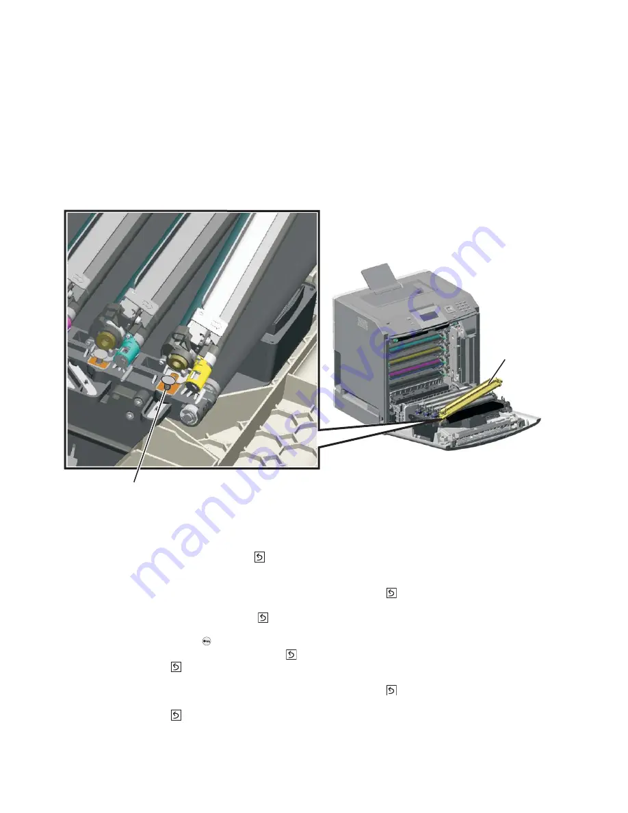
Photoconductor unit removal
Not a FRU
Warning:
To avoid damaging the photoconductor drum, hold the photoconductor units by their handle and
place the photoconductor units on a clean surface. See
“Handing the photoconductor unit” on
page 4-2
for additional information.
1.
Open the front access door.
2.
Lift the right end handle (A) of the photoconductor unit, releasing from the mount.
3.
Lift the unit up and away from the left side of printer, ensuring the left end of the photoconductor is released
from the holding pin (B).
Installation note:
If a new photoconductor unit is installed, reset the life count value in the printer memory.
•
If a message appears on the operator panel:
1.
When
84 <
color
> PC Unit Life Warning
or
84 Replace <
color
> PC Unit
appears, select
Supply
Replaced
, and then press
.
Replace Supply
displays.
2.
Select
Cyan PC Unit
,
Magenta PC Unit
,
Yellow PC Unit
, or
Black PC Unit
based on the
photoconductor unit that was just replaced, and then press
.
<
color
> PC Unit Replaced
displays.
3.
Select
Yes
, and then press
to clear the message.
•
If no message appears:
1.
Press
Menu
(
).
2.
Select
Supplies Menu
, and press
.
3.
Press
to
select
Replace Supply
.
4.
Select
Cyan PC Unit
,
Magenta PC Unit
,
Yellow PC Unit
, or
Black PC Unit
based on the
photoconductor unit that was just replaced, and then press
.
<color> PC Unit Replaced
displays.
Press
to
select
Yes
.
A
B
Summary of Contents for C734 series
Page 13: ...Notices and safety information xiii 5026 ...
Page 14: ...xiv Service Manual 5026 ...
Page 170: ...2 136 Service Manual 5026 ...
Page 288: ...4 72 Service Manual 5026 12 Remove the seven screws M securing the EP drive ...
Page 339: ...Repair information 4 123 5026 13 Remove the three printhead mounting screws D ...
Page 395: ...Connector locations 5 1 5026 5 Connector locations Locations ...
Page 408: ...7 2 Service Manual 5026 Assembly 1 Covers ...
Page 410: ...7 4 Service Manual 5026 Assembly 2 Front ...
Page 412: ...7 6 Service Manual 5026 Assembly 3 Right 1 2 3 4 5 6 ...
Page 414: ...7 8 Service Manual 5026 Assembly 4 Rear ...
Page 424: ...7 18 Service Manual 5026 Assembly 11 Options and features ...
Page 426: ...7 20 Service Manual 5026 ...
Page 436: ...I 10 Service Manual 5026 ...


