8400 StateLine C | Reference manual
Motor control (MCTRL)
Braking operation/brake energy management
226
L
Firmware
≤
11.00 - DMS 8.0 EN - 10/2011
5.11.2
Selecting the response to an increase of the DC-bus voltage
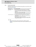
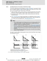
If the brake chopper threshold resulting from
C00173
and
C00174
is exceeded in the DC
bus, the reaction selected in
C00175
takes place (use of the brake resistor and/or stop of
the ramp function generator and/or inverter motor brake).
Optimum following of the actual speed value until the speed setpoint is reached (e.g.
the motor is stopped rapidly) is always achieved with the help of a brake resistor.
Stopping the ramp function generator enables smoother deceleration with lower
torque oscillation..
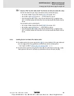
From version 04.00.00
, the inverter motor brake is available for selection in
C00175
.
This function enables rapid braking without a brake resistor. Torque oscillations can
occur due to the traversing dynamics.
Inverter motor brake
(
228)
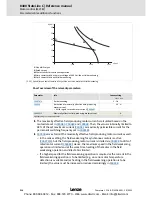
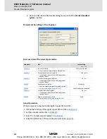
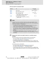
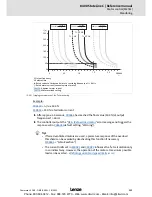
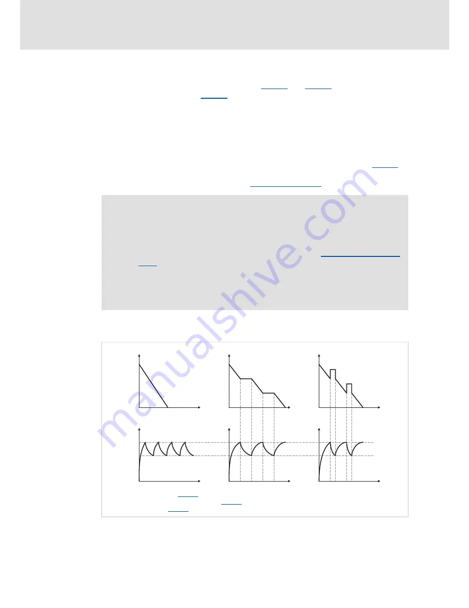
The way in which the different braking procedures work is demonstrated schematically in
the following illustration:
[5-26] Graph of the effective speed setpoint and the DC bus voltage during braking
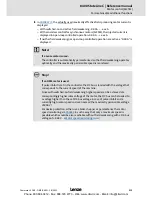
Stop!
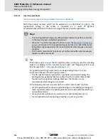
• The two braking procedures "Stopping of the ramp function generator" and
"Inverter motor brake" can only be used for speed-controlled applications
without the influence of a position controller!
• When the "inverter motor brake" function is used, the
Motor load monitoring
(I2xt)
is not adapted. If it is braked too frequently, there is a risk of the motor
being thermally overloaded or the motor overload monitoring does not work
properly!
• The "inverter motor brake" function must not be used with vertical conveyors
(hoists) or with active loads!
Use of the brake resistor (
C00175
= "0: Brake resistor")
Stopping of the ramp function generator (
C00175
= "1: HlgStop")
Inverter motor brake (
C00175
= "3: FI_ RfgStop)
n
Set
t
n
Set
t
1
2
n
Set
t
0
t
t
t
U
DC
U
DC
U
DC
Phone: 800.894.0412 - Fax: 888.723.4773 - Web: www.clrwtr.com - Email: [email protected]


