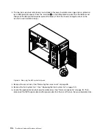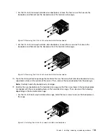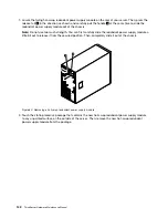
10. Connect the appropriate power cable
1
and the SATA signal cable
2
to the rear of the non-hot-swap
hard disk drive.
Figure 69. Connecting cables to the rear of the non-hot-swap hard disk drive
The following table provides information about the recommended power connector and system
board SATA connector for the non-hot-swap hard disk drive installed in each drive bay. See “Server
components” on page 25 and “System board components” on page 42 for the location information
about the hard disk drive bays and SATA connectors on the system board.
Non-hot-swap hard disk drive
Power connector
System board SATA connector
Installed in bay 0
P9 power connector
SATA connector 0
Installed in bay 1
P10 power connector
SATA connector 1
Installed in bay 2
P7 power connector
SATA connector 2
Installed in bay 3
P8 power connector
SATA connector 3
11. Connect the other end of the SATA signal cable to the appropriate SATA connector on the system board.
See “System board components” on page 42.
12. Reinstall the front system fan 1. See “Replacing the front system fan” on page 149.
132
ThinkServer Hardware Maintenance Manual
Summary of Contents for THINKSERVER 387
Page 16: ...4 ThinkServer Hardware Maintenance Manual ...
Page 18: ...6 ThinkServer Hardware Maintenance Manual ...
Page 94: ...82 ThinkServer Hardware Maintenance Manual ...
Page 190: ...178 ThinkServer Hardware Maintenance Manual ...
Page 228: ...216 ThinkServer Hardware Maintenance Manual ...
Page 246: ...234 ThinkServer Hardware Maintenance Manual ...
Page 247: ......
Page 248: ......


