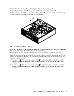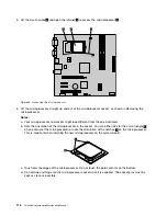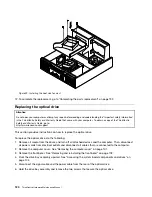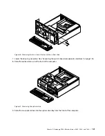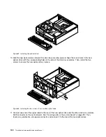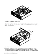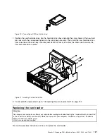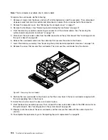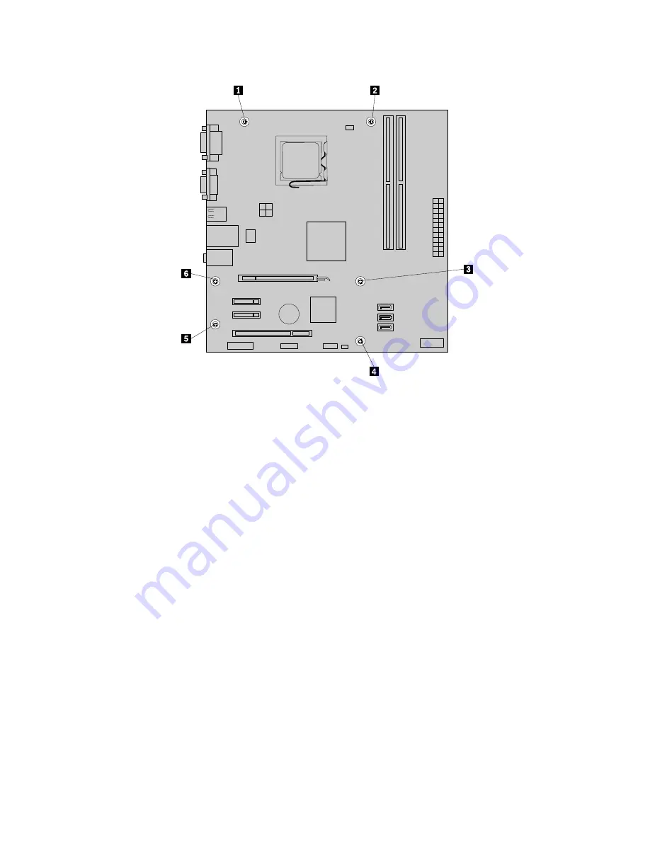
Figure 65. Removing the six screws that secure the system board
10. Lift the system board out of the chassis.
11. Remove the microprocessor from the failing system board and install it on the new system board. See
“Replacing the microprocessor” on page 113.
12. Install the new system board into the chassis by aligning the six mounting studs in the chassis with the
corresponding holes in the new system board. Then, install the six screws to secure the system board.
13. Install the heat sink and fan assembly and connect the heat sink and fan assembly cable to the new
system board. See “Replacing the heat sink and fan assembly” on page 110.
14. Install all memory modules and PCI cards removed from the failing system board on the new system
board. See “Installing or replacing a memory module” on page 107 and “Installing or replacing a PCI
card” on page 105.
15. Reconnect all remaining cables to the system board. See “Locating parts on the system board” on
page 99.
16. Lower the drive bay assembly. See “Accessing the system board components and drives” on page 104.
17. Reinstall the front bezel. See “Removing and reinstalling the front bezel” on page 102.
18. Reinstall the computer cover.
19. Go to “Completing the parts replacement” on page 132.
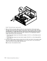
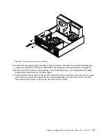
The failing system board must be returned with a microprocessor socket cover to protect the pins during
shipping and handling.
To install the microprocessor socket cover:
1. Remove the microprocessor from the microprocessor socket. See “Replacing the microprocessor” on
page 113.
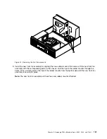
2. Close the microprocessor retainer and lock it into position with the small handle.
124
ThinkCentre Hardware Maintenance Manual
Summary of Contents for 7099U1U
Page 1: ...ThinkCentre Hardware Maintenance Manual Machine Types 0864 0889 5023 7099 7844 and 7846 ...
Page 2: ......
Page 3: ...ThinkCentre Hardware Maintenance Manual Machine Types 0864 0889 5023 7099 7844 and 7846 ...
Page 15: ...Chapter 2 Safety information 9 ...
Page 19: ...Chapter 2 Safety information 13 ...
Page 20: ...1 2 14 ThinkCentre Hardware Maintenance Manual ...
Page 21: ...Chapter 2 Safety information 15 ...
Page 27: ...Chapter 2 Safety information 21 ...
Page 31: ...Chapter 2 Safety information 25 ...
Page 72: ...66 ThinkCentre Hardware Maintenance Manual ...
Page 102: ...96 ThinkCentre Hardware Maintenance Manual ...
Page 218: ...212 ThinkCentre Hardware Maintenance Manual ...
Page 223: ......
Page 224: ...Part Number 89Y9149 Printed in USA 1P P N 89Y9149 89Y9149 ...


