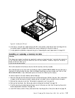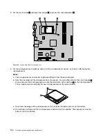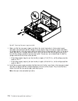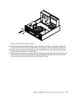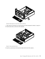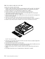
Figure 60. Removing the two screws that secure the optical drive
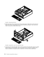
7. Lower the drive bay assembly. See “Accessing the system board components and drives” on page 104.
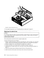
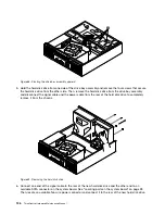
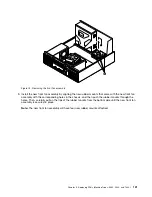
8. Slide the optical drive out of the front of the computer.
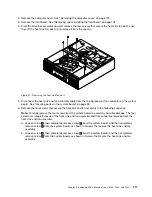
Figure 61. Removing the optical drive
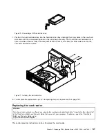
9. Slide the new optical drive into the optical drive bay from the front of the computer.
Chapter 9
.
Replacing FRUs (Machine Types: 0889, 5023, and 7844.)
121
Summary of Contents for 7099U1U
Page 1: ...ThinkCentre Hardware Maintenance Manual Machine Types 0864 0889 5023 7099 7844 and 7846 ...
Page 2: ......
Page 3: ...ThinkCentre Hardware Maintenance Manual Machine Types 0864 0889 5023 7099 7844 and 7846 ...
Page 15: ...Chapter 2 Safety information 9 ...
Page 19: ...Chapter 2 Safety information 13 ...
Page 20: ...1 2 14 ThinkCentre Hardware Maintenance Manual ...
Page 21: ...Chapter 2 Safety information 15 ...
Page 27: ...Chapter 2 Safety information 21 ...
Page 31: ...Chapter 2 Safety information 25 ...
Page 72: ...66 ThinkCentre Hardware Maintenance Manual ...
Page 102: ...96 ThinkCentre Hardware Maintenance Manual ...
Page 218: ...212 ThinkCentre Hardware Maintenance Manual ...
Page 223: ......
Page 224: ...Part Number 89Y9149 Printed in USA 1P P N 89Y9149 89Y9149 ...

