background image

Page 8

506393−01  11/2010

Blower Operation And Adjustments 

A−Three Phase Scroll Compressor Voltage Phasing

Three phase scroll compressors must be phased

sequentially to ensure correct compressor and blower

rotation and operation. Compressor and blower are wired

in phase at the factory. Power wires are color−coded as

follows: line 1−red, line 2−yellow, line 3−blue.

1− Observe suction and discharge pressures and

blower rotation on unit start−up.

2− Suction pressure must drop, discharge pressure

must rise, and blower rotation must match rotation
marking.

If pressure differential is not observed or blower rotation is

not correct:

3− Disconnect all remote electrical power supplies.

4− Reverse any two field−installed wires connected to

the line side of TB2. Do not reverse wires at blower
contactor.

5− Make sure the connections are tight.

Discharge and suction pressures should operate at

their normal start-up ranges.

B−Blower Operation

Initiate blower demand at thermostat according to

instructions provided with thermostat. Unit will cycle on

thermostat demand. The following steps apply to

applications using a typical electro−mechanical

thermostat.

1− Set thermostat or temperature control device fan

switch to 

AUTO

 or 

ON.

 With fan switch in 

ON

 position,

blower will operate continuously. With fan switch in

AUTO

 position, the blower will cycle with demand.

2− Blower and entire unit will be off when thermostat or

temperature control device system switch is in 

OFF

position.

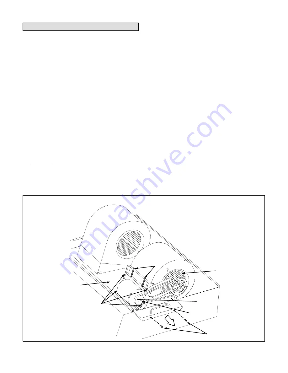
C−Blower Access

The blower assembly is secured to a sliding base which
allows the entire assembly to be pulled out of the unit. See
figure 5.

1− Remove the clamp which secures the blower wiring

to the blower motor base.

2− Remove and retain screws on either side of sliding

base. Pull base toward outside of unit. When pulling
the base out further than 12" (305mm), disconnect
wiring to K3 blower contactor T1, T2, and T3. Pull
wiring toward blower to allow enough slack to slide
the base out further.

BLOWER ASSEMBLY

TO INCREASE BELT TENSION

1− Loosen four screws securing blower motor to

sliding base.

2− Turn adjusting screw to the left, or counter-

clockwise, to move the motor downward and
tighten the belt.

3− Tighten four screws.

TO INCREASE CFM

LOOSEN ALLEN SCREW &

TURN PULLEY CLOCKWISE

TO DECREASE CFM

TURN PULLEY

COUNTERCLOCKWISE

FIGURE 5

BLOWER

WHEEL

BLOWER

MOTOR

PULLEY

ALLEN

SCREW

BLOWER ASSEMBLY

SLIDING BASE

BELT TENSION

ADJUSTING

SCREWS

LOOSEN (4) SCREWS TO

ADJUST BELT TENSION

REMOVE SCREWS TO

SLIDE BLOWER

ASSEMBLY OUT OF UNIT

Summary of Contents for KHA180

Page 1: ...contact with sharp edges INSTALLATION INSTRUCTIONS KHA180 15 TON KHA240 20 TON HEAT PUMP UNITS 506393 01 11 2010 Supersedes 10 2010 RETAIN THESE INSTRUCTIONS FOR FUTURE REFERENCE Table Of Contents Di...

Page 2: ...W 711 28 711 12 3 8 314 3 1 4 83 54 1 4 1378 51 1295 90 1 8 2289 29 1 4 743 91 1 8 2315 BASE CONDENSATE DRAIN 5 3 8 137 SIDE ELECTRICAL INLETS END VIEW SIDE VIEW 129 1 2 3289 BASE 128 1 2 3264 LIFTING...

Page 3: ...tallation of KHA heat pumps must conform with standards in National Fire Protection Association NFPA Standard for Installation of Air Conditioning and Ventilating Systems NFPA No 90A Standard for Inst...

Page 4: ...completion The unit components duct system air filters and evaporator coil must be thoroughly cleaned following final construction clean up The unit operating conditions including airflow cooling oper...

Page 5: ...rotection before rigging 2 Connect rigging to the unit base using both holes in each corner See figure 2 3 All panels must be in place for rigging 4 Place field provided H style pick in place just abo...

Page 6: ...y drafts or dead spots behind doors and in corners hot or cold air from ducts radiant heat from sun or appliances concealed pipes and chimneys B Control Wiring 1 Route thermostat cable or wires from s...

Page 7: ...installed for loose connections Tighten as required 3 Check to ensure that refrigerant lines do not rub against the cabinet or against other refrigerant lines 4 Check voltage at disconnect switch Volt...

Page 8: ...Set thermostat or temperature control device fan switch toAUTO or ON With fan switch in ON position blower will operate continuously With fan switch in AUTO position the blower will cycle with demand...

Page 9: ...um life and wear can be obtained from belts only if proper pulley alignment and belt tension are maintained Tension new belts after a 24 48 hour period of operation This will allow belt to stretch and...

Page 10: ...6750 665 2 20 745 2 70 815 3 20 880 3 70 940 4 20 995 4 65 1045 5 10 1095 5 60 1145 6 10 1190 6 60 1235 7 10 1275 7 60 7000 675 2 35 755 2 90 825 3 40 890 3 95 950 4 45 1005 4 95 1055 5 40 1105 5 95...

Page 11: ...07 08 5000 03 05 05 07 08 5250 03 06 05 07 09 5500 03 07 05 07 10 5750 03 07 05 08 11 6000 04 08 01 05 08 11 6250 04 08 01 01 05 08 12 6500 04 09 01 02 05 08 13 6750 05 10 01 03 05 08 14 7000 05 10 0...

Page 12: ...th an economizer when outdoor air is acceptable a first stage demand will energize the economizer a second stage demand will energize compressor 1 and outdoor fans 1 2 3 Refrigerant circuits are facto...

Page 13: ...alue shown indicates an overcharge 3 The approach method is not valid for grossly over or undercharged systems Use table 3 or 4 as a guide for typical operating pressures TABLE 5 APPROACH TEMPERATURES...

Page 14: ...e unit is in the heating mode and the defrost thermostat is closed or jumpered If the timing jumper is in the TEST position at power up the defrost control will ignore the test pins When the jumper is...

Page 15: ...ry two years with a lithium base grease such as Alvania 3 Shell Oil Chevron BRB2 Standard Oil or Regal AFB2 Texas Oil Use a hand grease gun for relubrication Add only enough grease to purge through th...

Page 16: ...ions 3 Remove wire ties connecting coils slabs and separate slabs 3 4 76 102mm 4 Clean coils with detergent or commercial coil cleaner 5 Rinse thoroughly with water and reassemble 6 Secure coil slabs...

Reviews: