36
6. Assembly
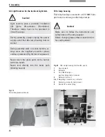
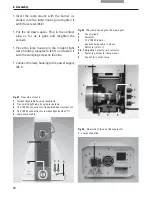
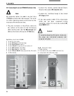
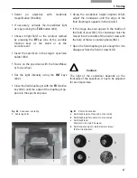
Fig. 39
Rear side of stand
1
RS232-interface
2
Connection to the Leica CTR6000 electronics box
3
Lamp power cable of the microscope
1
2
6.11 Connecting the Leica CTR6000 Electronics Box
Note:
We generally advise you
not
to use the Leica
CTR6000 box with other microscopes. The serial
no. of the matching stand can be found on the
rear side of the electronics box.
• Plug one connector of the 25-pin cable into
the socket on the back of the microscope
(39.2) and the other into the
Microscope
port
(38.6) on the back of the Leica CTR6000 box.
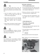
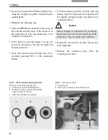
Fig. 38
Rear side of Leica CTR6000
1
Socket for mains cable
2
Socket
XY-Stage
for motorized stage
3
Socket
Direct interface
optional
4
Socket
Z-Control
for separate focus control unit
5
Socket
XYZ-Control
for SmartMove
6
Socket
Microscope
for microscope
7
Socket
12V, max 100W
for lamp power cable of the stand
8
DL: Reset button
7
1
2
3
4
5
8
6
• Connect the remote control element Smart-
Move to the socket
XYZ-Control
(38.5).
• Connect the motorized stage to the socket
XY-Stage
(38.2).
• If the lamp power cable of the microscope
(39.3) has not been connected during
assembly, connect it now to the socket
12V,
max 100W
(38.7).
Caution!
To avoid overheating of the ports, make sure
the plugs are connected properly and
screwed on tightly.
3

