background image

31

6. Assembly

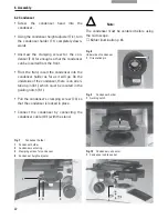
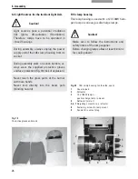
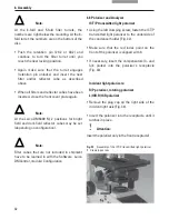
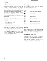
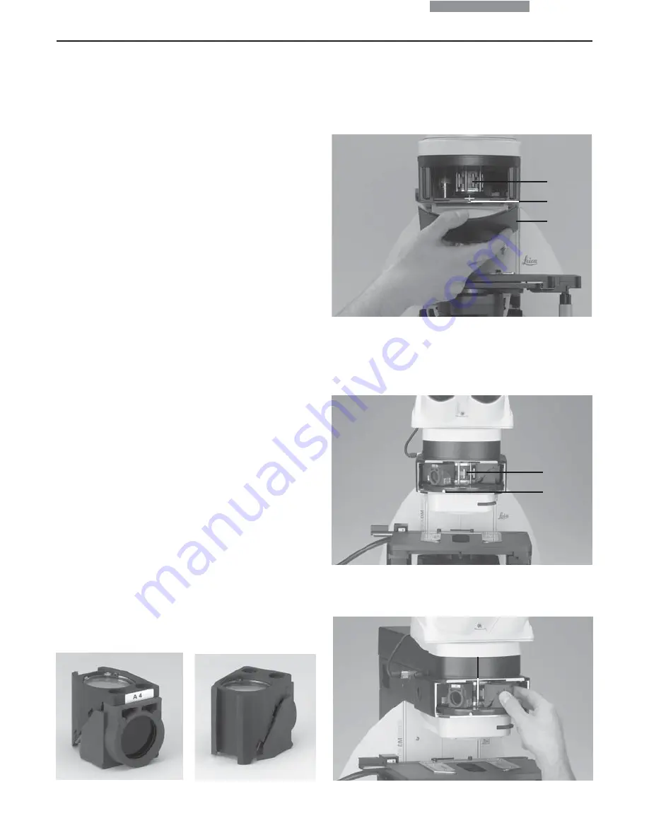
Fig. 29

Removing the front cover
(4-fold filter turret)

1

Filter receptacle

2

Retention pin

3

Front cover

1
2

6.7 Equipping the Incident Light Turret Disc

The receptacles on the turret are numbered.
According to your equipment, the individual
filter and/or reflector cubes have already pre-
assigned positions. A list is provided along with
your shipment (“identification sheet“).

Insert the filter and reflector cubes in the fol-
lowing manner:

• Equip the incident light turret only when the

microscope is switched off.

• Remove the front cover from the upper part of

the microscope (Fig. 29). Push the retention
pin (29.2 or 30.2) to move the turret.
Releasing the retention pin locks the turret.

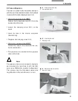
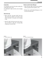
• Insert the filter or reflector cube  into the

mounting in front of you according to the
identification sheet provided.
To do so, place the filter or reflector cube on
the 

right

 side and press it to the 

left

 into the

mounting (Fig. 31).

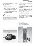
3

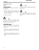
Fig. 30

8-fold filter turret
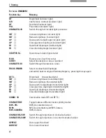
(front cover removed)

1

Filter receptacle

2

Retention pin

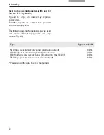
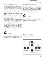
Fig. 31

Inserting the filter or reflector cubes

1

Mounting

1

1
2

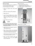
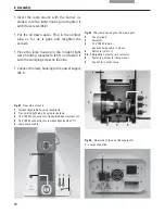
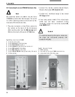
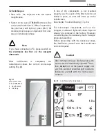
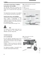
Fig. 27

Filter cube
front side

Fig. 28

Filter cube
back side

Summary of Contents for DM6000 M

Page 1: ...1 Leica DM6000B Leica DM6000M Operating Manual...

Page 2: ...etzlar Germany Responsible for contents Karin Schwab Marketing CM Compound Microscopy Product Management Holger Grasse Safety Officer according to MPG 30 In case of questions please contact the hotlin...

Page 3: ...3 Leica DM6000B Leica DM6000M Operating Manual...

Page 4: ...the Microsoft Corporation Otherwise no inference with regard to the free usability of product names may be drawn from the use of those names The instructions contained in the following documentation...

Page 5: ...8 8 Light Sources 66 8 9 Aperture Diaphragm and Field Diaphragm 67 Contents 1 Important Notes about this Manual 7 2 Intended Purpose of Microscopes 8 3 Safety Notes 9 3 1 General Safety Notes 9 3 2 El...

Page 6: ...Leica DM6000 M 74 10 1 Incident Light 74 10 1 1 Bright Field 74 10 1 2 Dark Field 74 10 1 3 Polarization 75 10 1 4 Interference Contrast 76 10 1 5 Fluorescence 76 10 2 Transmitted Light 77 10 2 1 Bri...

Page 7: ...erated incorrectly Explanatory note Item not contained in all configurations Text symbols pictograms and their meanings Caution This operating manual is an essential com ponent of the microscope and m...

Page 8: ...erning in vitro diagnostics They also conform to the Council Directives 73 23 EEC concerning electrical apparatus and 89 336 EEC concerning electromagnetic compatibility for use in an industrial envir...

Page 9: ...on the user must follow the instructions and warnings contained in this operating manual Caution The devices and accessories described in this operating manual have been tested for safety and potentia...

Page 10: ...any fuses as replacements other than those of the types and the current rat ings listed here Using patched fuses or bridging the fuse holder is not permitted 3 2 Electrical Safety General specificati...

Page 11: ...ion Protect the microscope from excessive tem perature fluctuations Such fluctuations can lead to the accumulation of condensation which can damage the electrical and optical components Ambient temper...

Page 12: ...Ma nager to control the fluores cence emission when using double and triple filter cubes motorized shutter speed 0 1s Leica DM6000 M transmitted light BF Pol incident light BF DF ICR DIC Pol Fluo inte...

Page 13: ...objectives with M32 thread mot DIC objective prism turret with 4 positions optional motorized condenser head automatic change between contrasting methods motorized condenser turret for light rings DF...

Page 14: ...configuration microscope and camera control image acquisition separate control unit to control z drive xy stage objective turret with supply voltage for 100W halogen lamp supply voltage for SmartMove...

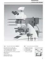
Page 15: ...15 4 Overview of the Instrument Fig 1 System overview DM6000 B with remote control element SmartMove and electronic box Leica CTR6000...

Page 16: ...with specimen holder 6 Condenser 7 LeicaScreen 1 2 3 4 5 6 7 8 9 10 11 12 13 14 8 Function keys field diaphragm 9 Transmitted light incident light switch 10 Function keys aperture diaphragm 11 Functi...

Page 17: ...r optional 19 Variable function keys factory pre assigned 20 Focus wheel 21 DIC turret 22 Motorized filter turret 23 Magnification changer 23 20 19 18 17 15 16 Fig 3 Right side of the stand Leica DM60...

Page 18: ...additional micro scope accessories such as filter cubes etc The CTR6000 Electronics Box the remote control element SmartMove and the external ebq 100 supply unit are delivered in separate packaging F...

Page 19: ...rm damp climatic zones require special care in order to prevent the build up of fungus See the chapter Care of the Microscope p 81 for additional instructions Caution Electrical components must be pla...

Page 20: ...er Tube Eyepieces Objectives Light sources Filter cubes reflectors Only a few commonly used screwdrivers and keys are necessary for assembly which are in cluded in the delivery package When using inte...

Page 21: ...re installed Place the specimen holder on the stage and fasten it with the two screws 5 1 Using the condenser height adjuster 5 2 turn the condenser holder completely upwards i e as close to the stage...

Page 22: ...re is an orien tation pin 8 1 which must be located in the guiding notch 9 1 Pull the condenser s clamping screw 7 3 so that the condenser is locked in place Connect the condenser by connecting the co...

Page 23: ...ring Retighten the clamping screw 12 1 Only for the motorized tube MBDT Connect the tube to the stand with the con nector socket 13 1 The eyepieces are inserted into the eyepiece tubes on the tube No...

Page 24: ...list of the exact objective positions is provided in shipment Identification Sheet Caution Cover unoccupied threads on the turret with dust protector caps Note We recommend to perform a parfocality ad...

Page 25: ...on the lamp Replace the housing and fasten it in place us ing the fastening screw Place the lamp housing in the transmitted light lamp housing receptacle 17 2 and fas ten it with the clamping screw o...

Page 26: ...glass parts of the burner with bare hands Never look directly into the beam path blinding hazard 106 z lamp housing This lamp housing is used with a 12V 100W halo gen lamp or various gas discharge la...

Page 27: ...t cover Reinsert the lamp mount and retighten the fastening screw 20 8 Close the lamp housing and retighten the fas tening screws Place the lamp housing in the incident light lamp housing receptacle 2...

Page 28: ...ollowing gas discharge lamps may be used and require different supply units and lamp mounts Fig 23 Type Typical bulb life 50 W high pressure mercury burner alternating current 100 hrs 100 W high press...

Page 29: ...housing unscrew the fastening screws on the cover Remove the transport anchorage red plastic rod in place of the burner in the lamp mount To do so remove the lower clamp 23 1 Pull up the cooling eleme...

Page 30: ...ping screw on the side Connect the lamp housing to the power supply 26 1 1 Fig 24 106 z lamp housing on the side open 1 Cover raised 2 Collector 3 12 V 100 W lamp or gas discharge lamp in mount 4 Refl...

Page 31: ...nt light turret only when the microscope is switched off Remove the front cover from the upper part of the microscope Fig 29 Push the retention pin 29 2 or 30 2 to move the turret Releasing the retent...

Page 32: ...ilter cubes that are not included in shipment have to be learned in with the Software Leica DMControl module Configuration 6 8 Polarizer and Analyzer ICT P transmitted light polarizer Using the left c...

Page 33: ...uipping the Incident Light Turret Disc p 31 in the corresponding position on the filter turret See the list provided Identification Sheet for the correct position Fig 34 Inserting the polarizer 1 The...

Page 34: ...with the Software Leica DMControl module Configuration Connecting two cameras The dual port enables you to connect two cameras one digital and one analog to the microscope When using a DC type digital...

Page 35: ...back of the stand and attach it using the side clamping screw Place the lamp housing onto the mirror hous ing and fasten it using the corresponding clamping screw on the side 1 1 Fig 36 1 Insert of B...

Page 36: ...CTR6000 box Fig 38 Rear side of Leica CTR6000 1 Socket for mains cable 2 Socket XY Stage for motorized stage 3 Socket Direct interface optional 4 Socket Z Control for separate focus control unit 5 So...

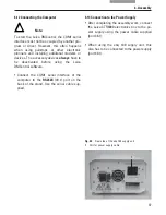
Page 37: ...ted before using the Leica DMControl software Connect the COM1 serial interface of the computer to the RS232C 39 1 port on the back of the stand Use the serial cable sup plied 6 13 Connection to the P...

Page 38: ...overwrites the previous settings Actual settings are stored automatically and can be recalled when switching on the microscope again 2 Control elements LeicaScreen Controls the microscope s functions...

Page 39: ...keys on the left stand section Switch on the stand Hold the keys pressed down until initialization is completed The standard information is shown in the LeicaScreen Switch off the instrument and switc...

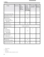
Page 40: ...Select objectives learn in parfocality change operating mode Dry Imm Illumination manager Magnification changer manual operation only Focusing 1 set thresholds go to thresholds change step size Coars...

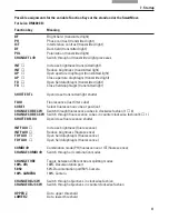
Page 41: ...luorescence last filter cube CUBE 1 Select fluorescence cube at position 1 CHANGE CUBE CW Switch through fluorescence cubes in clockwise fashion 1 4 CHANGE CUBE CCW Switch through fluorescence cubes i...

Page 42: ...Switch through fluorescence cubes FOCUS FINDER Select smallest field diaphragm and switch back to original field diaphragm by pressing the key again BF TL Bright field transmitted light INT Increase b...

Page 43: ...nted properly e g the cover of the filter turret is not locked in place an error will show up on the LeicaScreen See chapter Trouble Shooting p 80 The microscopic components such as dia phragms conden...

Page 44: ...l left column on the display the corresponding menu bar opens in the upper row of the display The items on the control panel change accordingly The currently active functions are highlighted in black...

Page 45: ...microscope configuration Defined Function Keys on the left side of the stand The TL IL key 43 1 switches between incident light and transmitted light The last contrast method used is restored The INT...

Page 46: ...the SmartMove The function keys are assigned logical functions before delivery corresponding to the configuration of your microscope The keys are labeled accordingly For the setting of the keys see I...

Page 47: ...condenser height adjuster 45 2 adjust the condenser until the edge of the field diaphragm appears in sharp relief If the image does not appear in the middle of the field of view 47c the condenser mus...

Page 48: ...us on the specimen with the SmartMove or focus wheel Adjust the light intensity with the INT keys 43 3 Adjusting the field diaphragm Close the field diaphragm with the FD keys 43 4 until the edge of t...

Page 49: ...the condenser The light rings are already centered in the factory However the centering should be rechecked Note Every objective is assigned its own light ring in the condenser disc Therefore a check...

Page 50: ...tering 1 Centering key 2 Opening for centering of motorized polarizer 1 Turn the centering screws until the dark ring phase ring in the objective is congruent with the slightly narrower bright ring li...

Page 51: ...lamp housing When a supply unit is used it is turned on first Activate the incident light axis using the TL IL function key FLUO Leica DM6000 B or IL Lei ca DM6000 M appears in the LeicaScreen Insert...

Page 52: ...direct arc image for gas discharge lamps and its mirror image are focused separately and adjusted to each other On the left side of the microscope there is an adjustment window 1 14 p 16 for mapping t...

Page 53: ...mirror image with the adjusting knobs 53 2 and 4 and focus it using the reflector 53 3 Align the mirror image symmetrically to the fil ament image Fig 56 To do so use the ad justing knobs 53 2 and 53...

Page 54: ...the centering plane Fig 58 Then pivot the arc s mirror image with the ad justing knobs 53 2 and 4 and focus it using the reflector 53 3 Use the adjusting knobs 53 2 and 4 to orient the mirror image sy...

Page 55: ...spot should lie slightly outside the center Fig 61 Then pivot the arc s mirror image with the ad justing knobs 53 2 and 53 4 and focus it us ing the reflector 53 3 Use the adjusting knobs 53 2 and 4...

Page 56: ...no longer be su perimposed exactly In this case align both images Using the collector defocus the image with the knob 53 6 until the arc image and mirror image are no longer recognizable and the im a...

Page 57: ...will light up green 64 2 Note If you have connected a PC please switch on the electronics box first and the computer afterwards All motorized components will run through an initializing phase Note If...

Page 58: ...the initialization is completed the status menu of the LeicaScreen Fig 65 shows the current microscope setting Note Reset Function The microscope can be reset to the default settings When the microsc...

Page 59: ...ntrol module DMOperation Store and recall stage positions With the Software Leica DMControl module DMOperation different stage positions can be temporarily stored Only the XY position is stored not th...

Page 60: ...with the LeicaScreen and with the Software Leica DMControl The lower threshold is the same for all objectives and can not be overrode Leica DM6000 B only An additional focus position which can not be...

Page 61: ...e Switch between Fine and Coarse via LeicaScreen navigation item Variable function keys at the stand and at the SmartMove Software Leica DMControl module DMOperation 8 4 Tubes Note Close any unused tu...

Page 62: ...BDT25 but it is motorized The control positions are displayed on the status page of the LeicaScreen After switching on the position 100 VIS is set automatically Fig 69 BDT25 tube with digital camera 1...

Page 63: ...ffect the Z position Note For eyepieces that are not included in delivery we recommend to learn them in with the Soft ware Leica DMControl module Configuration This ensures that the information about...

Page 64: ...from dry to immersion objectives In the reverse case the oil can be removed The current objective remains in the beam path Now press the button for the objective you want to select You can also press...

Page 65: ...the SmartMove Software Leica DMControl module DMOperation Note When retrofitting objectives they have to be learned in with the Software Leica DMControl module configuration Afterwards parfocality sh...

Page 66: ...for trans mitted light TL or incident light IL For TL and IL Settings can be made either in large or small increments Pushing both INT buttons simultaneously switches between coarse and fine setting T...

Page 67: ...phragm may be used to change each diaphragm s set ting at any time The display on the LeicaScreen menu page Light Fig 74 changes accordingly Caution When doing so old values are overwritten and the ne...

Page 68: ...If all positions at the filter turret are occupied the filter cube A can be exchanged for A TL with the Software Leica DMControl module Configuration TL contrasting methods are now possible Switch to...

Page 69: ...hragm is opened completely and can not be adjusted 9 1 3 Dark Field TL Switch to the transmitted light axis TL by pushing the TL IL button Select the DF dark field contrast method Do so by pressing th...

Page 70: ...ake sure that the red index point on the front of the polarizer is aligned with 0 Insert the analyzer into the left side of the stand 76 1 Bring the polarizer and analyzer into cross po sition until t...

Page 71: ...ated in the condenser and the fitting condenser prism are automatically brought into the light path The corresponding objective prism and the analyzer cube are also positioned automatically For fine a...

Page 72: ...tion item Variable function keys at the stand and at the SmartMove Cube CW or Cube CCW Software Leica DMControl module DMOperation Focus on the image with the turning knob on the SmartMove or with the...

Page 73: ...reen changes accordingly Insert a specimen and select an appropriate objective The required fluorescence cube can be selected with the variable function keys The illumination settings for the fluoresc...

Page 74: ...creen menu page Status indicates BF Insert a specimen Select an appropriate objective Focus on the image with the turning knob on the SmartMove or with the focus wheel and adjust the illumination with...

Page 75: ...LeicaScreen menu page Status indicates POL Automatic procedure The ICR filter cube is automatically brought into the light path Manual procedure Rotate the appropriate polarizer 80 3 and the IC P ana...

Page 76: ...Alternatively Rotate the ICR polarizer 80 1 and the IC P analyzer 81 1 on the stand manually into the light path Objectives and condenser prisms are swung into the beam path automatically For fine ad...

Page 77: ...by pressing the POL variable key Alternatively Press the CHANGE TL variable key For key occupation please see Identification Sheet The display of the LeicaScreen menu page Status indicates POL Manual...

Page 78: ...connections Inform service technician to change the fuses Open the shutter p 84 Check the connection of the lamp houses to the microscope Transmitted axis Reflected Fluo axis Make sure that the lamps...

Page 79: ...wards the top Make sure that the cover glass thickness is correct and that it suits the indication on the objective Be sure that a DF objective is being used The objective aperture setting is too hig...

Page 80: ...ross po sition until they reach maximum darkness without specimen p 70 75 Open the shutter p 72 Select the incident light axis IL p 45 Check the antigen antibody combination Insert a new lamp p 26f In...

Page 81: ...ion water may occur 12 2 Cleaning Caution Residual fiber and dust can create unwanted background fluorescence Cleaning Coated Parts Dust and loose dirt particles can be removed with a soft brush or li...

Page 82: ...ur Leica subsidiary for repair We also advise against cleaning the inside surfaces of the eyepieces The front lenses of objectives are cleaned as described under Cleaning Glass Surfaces The upper lens...

Page 83: ...00 139 High pressure xenon burner 75 W 106 z lamp housing Screw cap for unused objective receptacles 020 422 570 000 Screw cap M 25 Objective turret Replacement eyecup diaphragm protection for HC PLAN...

Page 84: ...tion port Stage and focus settings LeicaScreen configuration Lower threshold not set Lower threshold set Focus position not set Focus position not set Transmitted light shutter open Transmitted light...

Page 85: ...F Darkfield DIC Differential interference contrast FD Field diaphragm FLUO Fluo axis incident light ICR Interference contrast reflected light ICT Interference contrast transmitted light IL Incident li...

Page 86: ...Incident light polarizators 32 Incident light shutter 42 Initialization 43 58 Interference contrast 76 Intermediate systems 20 K hler illumination 22 46 Lamp housing 17 Lamp housing 106 z 26 51 Lamp...

Page 87: ...eby declare that the device described below both in its basic design and construction and in the version marked by us conforms to the relevant safety and health related requirements of the appropriate...

Reviews: