background image

Proline Kryomats


YAUE0007 / 2/26/2009 

Starting up


51


7.6 

Special settings 

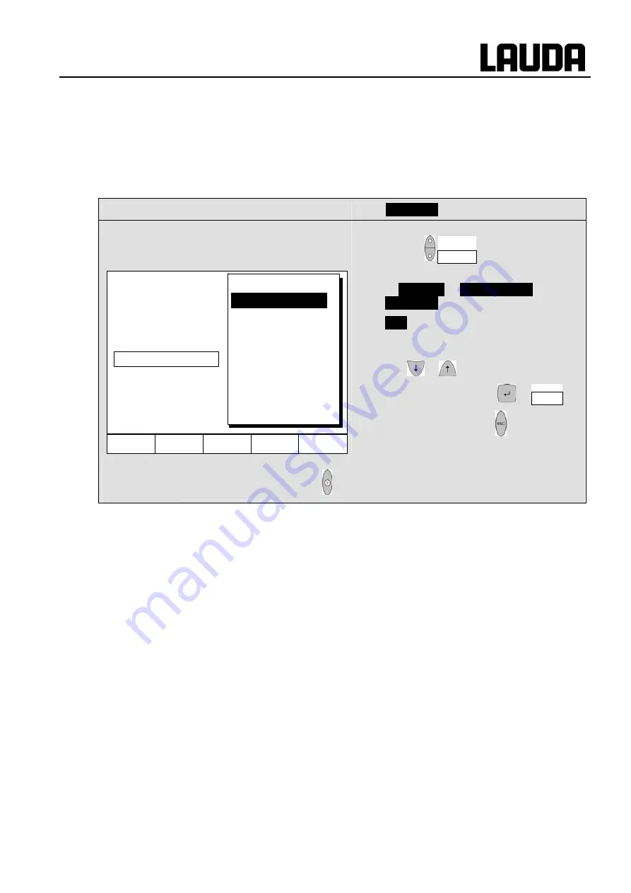
7.6.1  Defining the type of start mode 

Usually it is desirable that the thermostat carries on operating again after an interruption in the voltage 
supply. However, if for safety reasons you do not wish this, you can insert an intervening manual 
activation step. 

Command 


 Auto start 


  Open the device parameter menu via the 

soft key     Menu   . 

  With the cursor keys continue to: 

Æ


 Settings 


Æ


 Basic settings 


Æ


 Auto start 


 On 

 is currently active. 

  If the standby mode is to be activated 

after a mains interruption, activate "Off" 

with 

 or 

 . 

  Accept the change with 

 or   End   , 

  or quit the window with 

 without making 

changes. 

)


  When the mains voltage has been restored after an interruption, you can quit 

the standby mode with  . 


 Help Menu

End  T

set

T

fix


Off 

On                      


Display  
Sounds Master  
Sounds Command  
Language 
Master Mode  

Autostart                

Current consumpt. 
 

Summary of Contents for PROLINE Kryomats Series

Page 1: ...oenigshofen Germany from software version of Cooling system 2 27 from software version of Analogue interface 2 01 from software version of RS232 485 Module 2 00 from software version of contact I 0 module 2 00 Phone 0049 9343 503 0 Fax 0049 9343 503 222 E Mail info lauda de Internet http www lauda de Operating instructions PROLINE Kryomats Low temperature Thermostats with SmartCool System RP 3050 ...

Page 2: ......

Page 3: ...for servicing or repair moving the equipment Transport the equipment with care The unit may NEVER be overturned nor put upside down Equipment and its internal parts can be damaged by dropping by shock Technically qualified personnel must only operate the equipment Never operate the equipment without the heat transfer liquid Do not start up the equipment if it is damaged or leaking cable not only s...

Page 4: ...KING 21 5 1 AFTER UNPACKING 21 5 2 STANDARD ACCESSORIES 21 5 3 PACKING AND UNPACKING WITH ORIGINAL VERPACKUNGSMATERIAL 21 5 3 1 Background 21 5 3 2 Voraussetzungen 21 5 3 3 Auspacken des Gerätes 22 5 3 3 1 Umverpackung 22 5 3 3 2 Gerät von der Palette heben 24 5 3 3 3 Vor der Inbetriebnahme 25 6 PREPARATION 26 6 1 ASSEMBLY AND SITING 26 6 2 FILLING AND DRAINING 27 6 3 HEAT TRANSFER LIQUIDS AND HOS...

Page 5: ...IMER FUNCTION COMMAND 71 7 11 CONTROL PARAMETERS 72 7 11 1 Internal control variable integral measurement probe 73 7 11 1 1 Proven settings for control parameters and pump integral measurement probe 73 7 11 2 External control variable External measurement probe 73 7 11 2 1 Steps for setting the control parameters for external control 74 7 12 ALARMS WARNINGS AND ERRORS 75 7 12 1 Overtemperature pro...

Page 6: ...ooled condenser 99 9 3 4 2 Water cooled condenser 99 9 3 4 2 1 Cleaning the dirt trap 99 9 3 4 2 2 Decalcifying the water cooling circuit 100 9 3 5 Repair information 100 9 3 6 Disposal information 101 9 3 6 1 Disposal of the refrigerant 101 9 3 6 2 Disposal of the packaging 101 9 3 7 Remedying faults 102 9 4 HELP DESK AND ORDERING REPLACEMENT PARTS 104 10 ACCESSORIES 105 11 TECHNICAL DATA AND DIA...

Page 7: ...ss A digital devices This equipment has been tested and found to comply with the limits for Class A digital device pursuant to Part 15 of the FCC Federal Communication Commission Rules These limits are designed to provide reasonable protection against harmful interference when the equipment is operated in a commercial environment This equipment generates uses and can radiate radio frequency energy...

Page 8: ...oiling Withdraw the mains plug before cleaning maintenance or moving the thermostat Specialist personnel must only carry out repairs in the control section The following action may start the thermostat unintentionally from the standby mode Previously activated timer mode Ö 7 10 Start command via interfaces Ö 8 Figures of temperature constancy and display accuracy apply under normal conditions acco...

Page 9: ...ammable liquids to DIN EN 61010 2 010 Æ Take care of the level of the heat transfer liquid Ö 6 2 3 Compare the information on the rating label with the supply details 4 Connect the unit only to a socket with a protective earth PE connection 5 Check whether the switch at the back of the master control element is in the ON position 6 Check whether the switch at the front of the master control elemen...

Page 10: ...mp power 5 8 Standby 0 Os 7 C Setpoint RDr C Control Intern Extern Bml 0 C Further settings LMDkt C Configure modules LMnet C End Dlc C Display flashes Set setpoint with or Display is accepted after 4 sec or proceed immediately with the key Control parameters setpoint resolution setpoint source input calibration etc Protection system Command cooling system analog and RS232 digital module etc Exter...

Page 11: ...set Max Fan 60 Brightness Contrast intern Pt100 extern Pt100 Device type Software Version Serial numbers Device data Error store Mode Baud rate RS485 address internal external Pt100 Analog interface RS232 485 Calibration Default Alarm Warning all default Basic window Standard window Super window Edit Default T il min T ih max Xp Tn Tv auto Td auto Kpe Tne Tve auto Tde auto Xpf Prop_E a off externa...

Page 12: ...ypass valve see illustration on this page 5 Bath cover 6 Rotary switch for power supply 7 Front cover closed 8 Grille on both sides 9 Four steering transport rollers two off them with stoppers 1 2 3 Pump connection on the side 1 Suction nozzle return to bath Pump outflow or pressure output closed off with screw plug refer to housing for label 2 Bypass valve in external position 3 Pump outflow pres...

Page 13: ...Proline Kryomats YAUE0007 2 26 2009 Controls and functional elements 13 1 2 3 4 1 Front cover open 2 Bath drain tap 3 Bath drain nozzle 4 Condenser ...

Page 14: ...ls and functional elements YAUE0007 2 26 2009 1 2 3 4 5 6 1 Bath bridge heating 2 Rating label 3 Connection cable for control head 4 Connection cable LiBus 5 Cooling water connections at water cooled devices W only 6 Mains cable ...

Page 15: ...l Pt100 temperature probe 4 Connection socket 70S LAUDA internal bus LiBus for bus suitable for unit and to which the refrigerating lower section and Command Console are connected 5 Mains switch 6 Connection socket 51H 7 Air intake for electronic head 8 Pump connection rear and on the side Suction nozzle return to bath pump outflow or pressure output refer to housing for label 9 Mains connecting l...

Page 16: ...raphical display here in the standard window displaying the values Actual temperature Tint of internal bath temperature probe Setpoint temperature Tset Actual temperature Text of the external temperature probe Bath level Pump level Five soft key duo keys their associated functions are shown in the display Enter key Cursor key Decimal point or symbol Standby key brings the thermostat into the idle ...

Page 17: ... level 5 to 8 The pump power can therefore be optimally matched to the relevant task In order to achieve optimum temperature homogeneity in the heat transfer liquid in the bath it is recommended to select the pump level in dependence of the viscosity of the heat transfer liquid therefore at higher viscosity to increase the pump level Be cautious at higher bath levels to avoid liquid to slop over t...

Page 18: ...gh resolution A D converter processes the measurement Further measurement conditioning occurs using a special control algorithm for controlling the heater actuator which has a low reactive effect on the mains and the SmartCool refrigeration equipment together with further transducers An external Pt100 temperature probe can be connected via a socket 10S for the acquisition of an external temperatur...

Page 19: ...l element external solenoid valve etc An RS232 485 interface 65S at the back of the Command control element 4 8 Interface modules accessories The Master control element can be supplemented with further interface modules which are simply inserted into two module slots Ö 3 at the back of the control head The following modules are currently available 1 RS232 485 Interface Module Order No LRZ 913 with...

Page 20: ...o achieve this a number of sensors in the cooling circuit monitor the operating conditions The compressors are equipped with overtemperature cutouts which respond to the compressor temperature and the compressor current consumption In addition the refrigeration system is backed up by a pressure control device against over pressure The cooling unit is normally switched in automatically but can be s...

Page 21: ...Bath cover with grip for RP 3050 C RP 3050 CW RP 3090 C and RP 3090 CW HKM 032 4 Union nuts for olives M16 x 1 already mounted for all Kryomats HKN 065 4 Screw plugs for M16 x 1 already mounted for all Kryomats EOA 001 2 Threaded house coupling Nipple Nut G for water cooled devices only EZB 260 1 Warning label Hot surface for all Kryomats 5 3 Packing and Unpacking with original Verpackungsmaterial...

Page 22: ...Proline Kryomats 22 Unpacking YAUE0007 2 26 2009 5 3 3 Auspacken des Gerätes 5 3 3 1 Umverpackung Öffnen Sie oben den Karton Palette Entnehmen Sie das Füllmaterial und die Zubehörteile ...

Page 23: ...Proline Kryomats YAUE0007 26 02 09 4BUnpacking 23 Entfernen Sie die Nägel an den 4 Ecken welche den Karton auf der Palette fixieren Nehmen Sie den Karton senkrecht nach oben über das Gerät ab ...

Page 24: ...ischen Palette und den Rädern um das Gerät und führen Sie die Gurtschlaufen über der Gerätemitte zusammen Heben Sie das Gerät anschließend von der Palette Achtung Der Gurt darf nicht gegen den Aufbau des Gerätes drücken Watch for center of gravity Vorderansicht der Gurtverlegung Richten Sie ggf die Räder gerade aus ...

Page 25: ... Kryomats YAUE0007 26 02 09 4BUnpacking 25 Seitenansicht der Gurtverlegung 5 3 3 3 Vor der Inbetriebnahme Schutzfolie abnehmen Für die Aufstellung und die Inbetriebnahme ist die Bedienungsanleitung zu beachten ...

Page 26: ...it into the socket 52H on the back of the Kryomat Plug the LiBus connector of the Command control element into the 70S socket and secure it Plug the LiBus cable from the refrigerator unit also into the socket 70S on the back of the Master control element and secure it Operation with external loads Circulating thermostat continue at Ö 6 4 Check whether the pump connectors at the side and back are f...

Page 27: ...gher than 25 C below its fire point Ö 6 3 When using heat transfer oils note that they expand on heating approx 10 100 K With enclosed external loads the overall expansion takes place in the bath of the Proline Kryomat Ensure that with the connection of an external load the liquid level does not drop impermissibly due to filling the load Æ top up with liquid if necessary Set the upper and lower te...

Page 28: ...288 LZB 114 LZB 214 LZB 314 Therm 200 60 200 Silicone oil 54 28 at 60 C 362 LZB 117 LZB 217 LZB 317 Therm 240 50 240 Silicone oil 130 45 at 50 C 378 LZB 122 LZB 222 LZB 322 c At higher temperatures Æ Evaporation losses Æ Use bath covers Only use distilled water or fully demineralized high purity water after adding 0 1 g of soda Na2CO3 sodium carbonate liter of water Æ Risk of corrosion d Water con...

Page 29: ...glycol mixture LZS 007 Viton 11 10 200 For all heat transfer liquids RKJ 091 Viton insulated 11 External Ø approx 32mm 20 200 For all heat transfer liquids LZS 018 EPDM hose is not suitable for Ultra 350 and not suitable for mineral oils With silicone rubber silicone oils lead to substantial swelling Æ never use silicone oil with silicone hoses Secure hoses against slippage with hose clips b Metal...

Page 30: ...ation must not have a hydraulically blocking effect If cross sectional area of tube is too low Æ temperature gradient between bath and external load due to low flow rate Always ensure the largest possible passages in the external circuit When tightening the union nuts on the pump nipple AF 19 use a wrench AF 14 to counter the tightening torque see figure If external control is to be used provide a...

Page 31: ... this equipment in a residential area is likely to cause harmful interference in which case the user will be required to correct the interference at his own expense This device complies with Part 15 of the FCC Federal Communication Commission Rules Operation is subject to the following two conditions 1 This device may not cause harmful interference and 2 this device must accept any interference re...

Page 32: ...off Ö 7 12 1 Overtemperature protection and checking on page 75 If necessary top up heat transfer liquid this has been pumped out by filling the external load Display for KDTDK low level appears when the bath has too little liquid Red LED above the fault triangle flashes Find cause of fault and where necessary top up missing heat transfer liquid Ö 6 3 Press the Enter key Also press the key if unit...

Page 33: ...sing the switch at the front or back there is still voltage present on the unit or head Standby operation Use the key standby Ö 7 5 3 on the command control element The pump heating and cooling unit are switched off but the operating display remains active so that status displays can be viewed and settings carried out However a started timer Ö 7 10 continues to run Stop as required with Pause Help...

Page 34: ... to the right occurs by briefly 1 second releasing the key followed by another pressing of the key Useful additional information two dots in the Master display indicate that a submenu follows Three dots in the display indicate that a submenu for a module interface or a component thermostat Command control element follows Module component specific possible settings are only displayed when the hardw...

Page 35: ...ich each have the function shown in display above them Soft key entries are shown framed in the operating instructions Example You would like to change the setpoint temperature then press the duo key under Tset Brightness Contrast The brightness and contrast can be set on the Command Console The works setting can be changed via Æ Settings Æ Basic settings Æ Display Æ Brightness or Æ Contrast The b...

Page 36: ...een basic normal super and graphics recorder windows Tset Changes setpoint temperature Tfix Calling and setting of saved setpoints 2 Standard window with five important items of information Tint current bath temperature Tset setpoint Text current temperature on external probe if connected Level of heat transfer liquid in cm above the minimum level Pump level of the VarioFlex Pump Soft keys like ab...

Page 37: ...onnected Overtemperature cut off point Tmax Pump level of the VarioFlex Pump Control variable to Tint or Text Information Heating cooling Soft keys like above 4 Graphical measurement display All temperature values can be shown graphically against time Ö 7 7 Soft keys like above Help Menu Screen Tset Tfix Tint C 25 01 Tset C 25 00 Tmax C 130 Pump 3 Control Var Tint Text C 25 02 55 3 Y 0 0 ...

Page 38: ...Open the unit parameter menu via the soft key Menu With and change from Settings Æ Display Data Æ Standard Window Æ Edit or takes you to the illustrated window and marks T max as illustrated Confirm selection with or End or quit the window with without any changes being made Help Menu Screen Tset Tfix Tint C 25 01 Tset C 25 00 Level 4 Text C 25 02 Pump 3 Help Menu End Tset Tfix Edit Default Basic ...

Page 39: ...R ED Locking and hold pressed simultane ously for 3 s RDr appears for 3 seconds then the segments of the first right hand are formed hold both keys pressed until this display is completely visible R ED flashes briefly and the display returns to the actual temperature The Master keyboard is now locked The R ED display signals the locked state when any Master key is pressed Unlocking and hold presse...

Page 40: ...the previously set Screen mode The soft key boxes are now blank indicating that the keyboard is locked On pressing any Master key the display appears Keyboard locked Unlocking Press and then and hold pressed simultaneously for three seconds The unlocking window appears Hold both keys pressed until the progress bar is completely filled Then the display skips back to the previously set Screen mode H...

Page 41: ... pilot lamps Wait 4 seconds or Display flashes 4 seconds Æ new value is automatically accepted or value is accepted immediately with Enter key For safety reasons the setpoint can only be set up to 2 C above upper limit of the operating temperature range for the relevant device type In the following cases the manual setpoint entry is blocked Setpoint is taken from the analog module from the program...

Page 42: ...ange it with or Confirm the value with or quit the window with without having made any changes Two other ways of entering the setpoint With the soft key Tfix open the window shown on the left The setpoints which you last entered are shown in the right hand column In the illustrated screen the last setpoint was 80 0 C To accept an earlier setpoint enter the right hand column with and select the des...

Page 43: ...channel 2 can be used as the controlled variable for the bath temperature in applications with a noticeable temperature gradient between the internal bath temperature and an external load The setup is described in Section 7 5 4 With the function described in the following you only change over the display External actual temperatures can also be read in by interface modules Ö 8 Connection of the ex...

Page 44: ...ia interface modules Ö 8 7 5 3 Setting pump power or standby With the Proline VarioFlex pump four pump levels level five till level eight are available with which the bath circulation flow rate and pressure the noise generated and the mechanical heat input can be optimized Pump level eight gives the best bath circulation and temperature homogeneity Master Os and 1 x Call pump power levels display ...

Page 45: ... the window with without making any changes It is not possible to select the pump levels 1 to 4 Standby activation Standby activation Pump heater and refrigerating machine are deactivated when the green LED in the lower part of the key is lit Please exercise caution when thermostat is in standby mode The following settings actions may start the thermostat unintentionally from the standby mode a pr...

Page 46: ...ut making any changes Automatic mode means that the external pump is switched off while the unit is in standby mode or it is switched on while the unit is running 7 5 5 Activating external control An external temperature probe can be connected to the Proline Thermostats How this is done is explained in Section 7 5 2 If the bath temperature is to be controlled using this sensor instead of the inter...

Page 47: ...re probe source 0 for the internal probe DO only when an external probe is connected D only when an analog module is connected and configured DR only when a serial module is connected and is continuously receiving actual values from a PC Wait 4 seconds or Display flashes 4 s Æ new value is automatically accepted or value is immediately accepted with Enter key If DO D or DR has been selected then t...

Page 48: ...enu via the soft key Menu With the cursor keys change further to Æ Settings Æ Basic settings Æ Current Consumpt 16 0 A is active Open the settings window with Changes are not accepted Quit the window with Help Menu End Tset Tfix 16 0 A Display Sounds Master Sounds Command Language Master Mode Autostart Current consumpt Help Menu Screen Tset Tfix 6 7 8 9 0 1 2 3 4 5 Max current consumption in A 16 ...

Page 49: ...tings window with Change the time with cursor or soft keys and accept with or quit the window with without making changes The date is set just the same with Set date The date format Day Month Year or Month Day Year can be set under Format of date Help Menu Screen Tset Tfix 6 7 8 9 0 1 2 3 4 5 Enter time 15 38 12 Help Menu End Tset Tfix Set time Set date Timer 1 Timer 2 Format of date Pump Settings...

Page 50: ... the soft key Menu With the cursor keys continue to Æ Settings Æ Display resolution Select the desired resolution with or Accept selection with or End or quit the window with without making any changes Help Menu End Tset Tfix Calibration Works settings Resolution Device status Display data Basic settings Overlevel handling Pump Settings Graph Clock Programmer Interfaces Control Limits Help Menu En...

Page 51: ...Auto start Open the device parameter menu via the soft key Menu With the cursor keys continue to Æ Settings Æ Basic settings Æ Auto start On is currently active If the standby mode is to be activated after a mains interruption activate Off with or Accept the change with or End or quit the window with without making changes When the mains voltage has been restored after an interruption you can quit...

Page 52: ...cticable as the maximum temperature and 5 C as the minimum temperature Command Limits Open the device parameter menu via the soft key Menu With the cursor keys continue to Limits The minimum and maximum temperatures are displayed T il min is currently active Select the limit to be changed with or and confirm with Enter the desired limit temperature Accept the change with or quit the window with wi...

Page 53: ...sor keys continue to Æ Control Æ Setpoint offset Æ Offset source Off indicates that the setpoint offset is currently deactivated Select the setpoint source with or and confirm with Interfaces e g RS232 are only displayed if a valid setpoint has already been transmitted With the cursor keys continue to Æ Setpoint offset The standard value is 0 00 C Open the left hand window with Enter the desired t...

Page 54: ...eset to the works setting with all default Under Master you have the choice between all default then all Master settings are reset only control para int for the internal control parameters only control para ext similar for external only miscellaneous which resets setpoint pump level maximum current consumption control to internal and auto start to Auto Under Command all command settings are reset ...

Page 55: ...e offset of the internal temperature probe If during checking with a calibrated reference thermometer e g from the LAUDA DigiCal Series a deviation is found then the offset i e the additive part of the characteristic of the internal measuring chain can be adjusted with the following function The reference thermometer must be dipped into the bath according to the details on the calibration certific...

Page 56: ...intentionally the works setting can be restored with this function Command Default Open the device parameter menu via the soft key Menu With the cursor keys continue to Æ Settings Æ Calibration Æ intern Pt100 Æ Default The window shown adjacent appears Confirm selection with Confirm the control dialog on the right with or cancel with Return to the measurement window with End or Help Menu Screen Ts...

Page 57: ...u With the cursor keys continue to Æ Settings Æ Calibration Æ extern Pt100 Æ Calibration The adjacent window appears Confirm selection with Continue as described in Ö 7 6 6 for the internal temperature probe 7 6 9 Restoring the works setting of the external temperature probe offset If the offset has been misadjusted unintentionally the works setting can be restored with this function Command Defau...

Page 58: ...the axis label is to be invisible or visible Sample time defines with which time interval the measurements are recorded 5 possibilities are offered From 2s max 1h45min up to 2min max 105h Time axis defines over which time range the measurements are to be displayed With Automatic the program finds the optimum display Manual input from 9min up to 144h Time base defines whether scaling is to be carri...

Page 59: ...ged with Enter the desired new value in the changes window in the usual way When setting the minimum value the largest permissible value here 26 90 C since the maximum value is 27 C is stated When setting the maximum value it is conversely the minimum value which is entered However if a value is entered which exceeds the other corresponding limit then this warning is issued Warning Value not in in...

Page 60: ...ramp which is described by the target temperature i e the temperature at the end of the segment and the duration from the start to the end of the segment Step Without any specified time the final temperature is approached as quickly as possible Temperature hold phase No temperature change i e the temperatures at the start and end of a segment are the same The programmer can be controlled or change...

Page 61: ...erance Ö Section 7 8 4 The field tolerance refer to the above program table and the graph below It facilitates exact conformance to the dwell time at a specified temperature Segment 1 is not processed until the bath temperature is within the tolerance range n so that the ramp Segment 2 starts delayed at o A tolerance range which is too tight can however also cause undesired delays In particular wi...

Page 62: ...ram can be 1 started Start 2 paused Hold 3 continued Continue or 4 terminated Stop In addition the standby key stops the programmer Pause operation After standby is deactivated the programmer goes on Commands which depending on the situation cannot be executed are not displayed Continue therefore only appears when Hold has been activated Once the start has been confirmed with Prog 1 running appear...

Page 63: ...e last setpoint setting Continuation of a program paused with Hold occurs using Continue which is obtained with In addition the standby key stops the programmer The pump heater and cooling unit are switched off Follow the safety information Ö 7 5 3 After pressing the standby key again the programmer returns to the previously selected operating mode Pause or active operation depending on what was p...

Page 64: ...rently running segment are possible The segment then continues as though the modification had been applicable since the start of the segment However If the new segment time is shorter than the segment time that has already run then the program skips to the next segment If a segment time 999h 59min is required then this time period must be shared over a number of consecutive segments Entering a pro...

Page 65: ...ment 1 was created in this way Continue with to the fields Ö Time Ö Tolerance See program example in 7 8 1 If there is no entry in the Time field the bath temperature is approached as quickly as possible With a time entry the final temperature is obtained exactly after the time expires ramp The entry in the field Tolerance field defines how accurately the final temperature is to be obtained before...

Page 66: ...appears Then the final temperature is approached as quickly as possible With a time entry the final temperature is obtained exactly after the time expires ramp Enter the segment time and confirm with the key Continue to the Tolerance entry field with If the field in the column Tolerance has a black background the entry mode for the Temperature tolerance is obtained by pressing the key It defines h...

Page 67: ...ts of the contact module if present special accessory are programmed here If the field in the column Out 1 has a black background the entry mode for the Contact output is obtained by pressing the key With or select Open or Closed and confirm with stands for no change with respect to the previous segment i e if is present in all fields the contact setting of the start setting or that from the progr...

Page 68: ...s the program to repeat continuously Confirm the entry with the key and return to the display You can quit the Edit mode with or End 7 8 6 Viewing the program sequence as a graph Graph Command Programmer Program1 Graph takes you to the submenu Graph Press the key Ö Show chart and The program sequence is shown Help Menu End Tset Tfix Status Edit Loops Graph Info 1 Help Menu End Tset Tfix Status Edi...

Page 69: ...thout the time which is necessary to process step changes in temperature Number of free segments Segment which is at present currently being processed Residual time of the current segment in hours and minutes Current pass in the example the third of all passes is running The last three points are only displayed when a program runs Quit the window with or End T C Help Menu End Tset Tfix 27 00 26 00...

Page 70: ...7 6 2 are attained Command Ramp function Open the list of device parameters using the soft key Menu With the cursor keys continue to Æ Programmer Æ Ramp function Confirm with the key Enter a positive or negative temperature value with Temp change With Time enter a figure without time unit With Time unit choose between Second s up to Day s Under Status the ramp is started Æ Start or stopped Æ Stop ...

Page 71: ...he thermostat again from the standby mode The menu Function is used to define when an action is executed Similar to an electronic mains timer Weekplan enables two switching events to be carried out each day The cycle is repeated after 7 days Time absolute defines a time and a date on which a once only action switching event occurs The time point is set with Set time and with Set date Time relative...

Page 72: ...or operation as a bath thermostat with water as the bath medium with internal control The parameters are also preset for the operation of external containers with external control Sometimes however the operation of external containers requires adaptation In addition the thermal capacity and viscosity of the heat transfer liquid sometimes require adaptation The intelligent menu guidance with the Ma...

Page 73: ...ed 7 11 2 External control variable External measurement probe You only need to read further here if you have connected an external temperature probe or the actual temperature is read in from a module and you have activated it as control variable according to Section 7 5 4 Only modify the control parameters if you have knowledge of control techniques The control system for external actual values i...

Page 74: ...fer liquid with low viscosity and high thermal capacity Ranking water ethanol water glycol oil Fluorinert Set pump level as high as possible make bath circulation strong and fast choose hose length as short as possible i e 2 x 1m choose hose cross section as large as possible i e inch throughput through the external load as large as possible 2 2 Xpf setting when oscillating with short period occur...

Page 75: ...or errors as appropriate All warnings and alarms are shown on the Command control element in plain text Errors are shown in plain text on the Command control element also in an error list Alarms Alarms are safety relevant Pump heater and refrigerating unit will be shut off Warnings Warnings normally are not safety relevant The device continues to operate Errors If an error occurs the pump heater a...

Page 76: ... keep pressed This somewhat complicated procedure is intended to prevent unintentional adjustment Not higher than 25 C below the fire point of the heat transfer liquid used Ö 6 2 and 6 3 The setting range is restricted to 5 C above the upper limit of the working temperature range Tih Ö 7 6 2 If the bath temperature rises above the overtemperature cut off 1 Alarm sounds as dual tone signal 2 rDLMO ...

Page 77: ...riangle flashes Æ Heater switches off on both poles Æ VarioFlex pump and refrigerating unit are switched off Find the cause of the fault and where necessary top up for missing liquid Ö 6 2 and 6 3 Press the Enter key Also press this key if the unit has been switched off in the fault state Checking the safety system at regular intervals by lowering the bath level To do this fit a hose to the drain ...

Page 78: ...atures above 100 C Alarm lG K Alarm Alarm switches off the pump and the heater until the alarm is removed by pressing on the Master keyboard Recommended for external loads and flammable liquids Command Over level handling Open the device parameter menu via the soft key Menu With the cursor keys continue to Æ Settings Æ Over level handling The shown window appears Select the preferred parameter wit...

Page 79: ...ws Warning To release press Enter key Security 3 Level too high or Alarm AL 6 Level too high is shown in the display and signifies that unlocking is only possible on the Master control panel 7 12 5 Pump motor supervision Overload or blockage The SelfCheck Assistant monitors the VarioFlex Pump 1 Alarm sounds as dual tone signal for pump motor overload or blockage 2 Display of aK B signals blockage ...

Page 80: ...Alarm Low level pump is shown in the display and signifies that unlocking is only possible on the Master control panel 7 12 7 Compressor Overtemp Command Error Comp1 overtemp Error Comp1 overtemp is shown in the display The cause may be a technical malfunction or an extremly situation in temperature control Switch off the unit and wait min 15 minutes to restart it again so that the compressor has ...

Page 81: ...3 break VW 00 Software version of protection system too old VW00 Software version of control system too old VW 01 Software version of operating system too old VW001 Software version of operating system too old VW 02 Software version of heating system too old VW002 Software version of heating system too old VW 03 Software version of analogue Interface too old VW003 Software version of analogue inte...

Page 82: ...mp 1 too old VW211 Software version of pump 1 too old VW112 Software version of pump 2 too old VW212 Software version of pump 2 too old VW113 Software version of pump 3 too old VW213 Software version of pump 3 too old Warnings from Analogue Module Warnings from RS232 485 Module Message Meaning Message Meaning VW3 0 Overflow of CAN receipt VW4 0 Overflow of CAN receipt VW3 1 Watchdog Reset VW4 1 Wa...

Page 83: ...em too old VW602 Software version of heating system too old VW503 Software version of analogue interface too old VW603 Software version of analogue interface too old VW504 Software version of RS232 too old VW604 Software version of RS232 too old VW506 Software version of valve 0 too old VW605 Software version of contact I 0 too old VW507 Software version of valve 1 too old VW508 Software version o...

Page 84: ...andshake Use screened connecting cable Connect screen to connector case The connections are galvanically isolated from the rest of the electronics Any pins not in use must not be connected When a PC is connected up the RS232 interface can easily be tested using the Microsoft Windows operating system On Windows 95 98 NT XP with the Hyper Terminal program 7 13 2 Protocol RS 232 The interface operate...

Page 85: ...n the form of a termination network which ensures a defined rest status in the high resistance phases of bus operation The bus termination is as follows This termination network is usually incorporated on the PC plug in card RS 485 7 13 4 Protocol RS 485 The interface operates with one stop bit no parity bit and 8 data bits Transfer rate either 2400 4800 9600 Factory setting or 19200 baud as selec...

Page 86: ...PAR_10_XXX X Setting of control parameter XpF OUT_PAR_11_XXX Setting of control parameter TnF 5 180s 181 Off OUT_PAR_12_XXX Setting of control parameter TvF OUT_PAR_13_XXX X Setting of control parameter TdF OUT_PAR_14_XXX X Setting of the setpoint offset OUT_MODE_00_X Keys Master 0 free 1 inhibited corresponds to KEY OUT_MODE_01_X Control 0 internal 1 external Pt100 2 external Analogue 3 external ...

Page 87: ...IN_SP_00 Read temperature setpoint IN_SP_01 Read current pump power stage IN_SP_02 Read cooling operation mode 0 OFF 1 ON 2 AUTOMATIC IN_SP_03 Read current overtemperature switch off point IN_SP_04 Read current outflow temperature limit TiH IN_SP_05 Read current outflow temperature limit TiL IN_PAR_00 Read current value of Xp IN_PAR_01 Read current value of Tn 181 OFF IN_PAR_02 Read current value ...

Page 88: ...noid valve Level controller STATUS Read equipment status 0 OK 1 error STAT Read error diagnosis response XXXXXXX X 0 no error X 1 error 1 Char error 2 Char Alarm 3 Char Warning 4 Char over temperature 5 Char low level error 6 Char high level error at adjustment alarm 7 Char no external control variable RMP_IN_00_XXX Read a program segment XXX response e g 030 00_010 00 Æ set point temperature 30 0...

Page 89: ...int input ON ERR_32 TiH TiL ERR_33 No external sensor ERR_34 Analogue value not available ERR_35 Auto is selected ERR_36 No set point input possible Programmer is running or is pausing ERR_37 No start from programmer possible analogue setpoint input is switched on 7 13 8 Driver software for LABVIEW An individual easy to use control and automation software for operating the PROLINE device can be pr...

Page 90: ...the rotary switch on the front panel and withdraw the mains plug Touch the earthed bath cover of the Proline thermostat to discharge any electrostatic charge Remove the module from its packaging Insert a screwdriver into the lower recess of the module cavity and prise up the plastic cover The cover can then be pulled off downwards Pull out the plug of the bus connecting cable from the plastic cove...

Page 91: ...serial Actuating signal Pump power Pump speed 2400 4800 9600 19200 Mode Baud rate RS485 address Voltage 0 10V Current 0 20mA Current 4 20mA Status Function Interface type Minimum value Maximum value Calibration Off On Voltage 0 10V Current 0 20mA Current 4 20mA Function Contact open Contact closed Off Fault Standby c Programmer Alternating mode Control type Only if setpoint temp alternating mode i...

Page 92: ...erature with function LM rD or ext actual temperature Pump power with function LM OO or Pump power The following values can be specified via the outputs Setpoint temperature with function Master LM rR or Command Set temperature The temperature source with which active control occurs LM rB Controlled temp Actual temperature bath temperature LM r0 or Internal Temp External actual temperature from Pt...

Page 93: ...ogrammer 1 input 2 activates programmer 2 etc At the first close the programmer gets starting open removes it in pause The next close initiate continue with function E Op5 or Programmer Control alternating mode the switching state contact open or closed allot to two different setpoint temperatures E r1B or alternating mode Controller mode the switching state input open or closed can allotted to tw...

Page 94: ...ctor to NAMUR NE28 Functionality as LRZ 915 but only one output and one input on each of two DIN sockets Contact inputs and outputs Output Input View on flange plug Front or solder side coupler socket Max 30 V 0 2 A Coupler socket Catalogue number EQD 047 View on flange plug Front or solder side coupler socket Signal circa 5 V 10 mA Do not use pin 3 Coupling plug Catalogue number EQS 048 1 n o mak...

Page 95: ...e displayed 9 1 4 Device data Command Device data Æ Settings Æ Device status Æ Device data Æ Display T ext shows various actual temperatures in C from ext Pt100 and the modules T cont head and T heatsink are temperatures of electronics in the Master in C Pump power in Watts speed in rpm current in ampere A Tint indicates the current internal bath temperature in C Mains voltage in percentage of nom...

Page 96: ...9 2 Cleaning 9 2 1 Cleaning the surface of the device Withdraw the equipment mains plug before cleaning Cleaning can be carried out with water to which a few drops of surfactant washing up liquid have been added and using a damp cloth No water must enter the control section Carry out appropriate decontamination if hazardous material is spilt on or in the equipment The cleaning or decontamination m...

Page 97: ...aning repair and disposal information Withdraw the mains plug before all service and repair work Only specialists must carry out repairs in the control section 9 3 1 Servicing LAUDA Thermostats largely require no service If the heat transfer liquid becomes contaminated it should be replaced Ö 6 2 At the back of the Master head a main fuse switch is located which interrupts the mains connection whe...

Page 98: ...visual inspection Cooling unit Condenser cleaning Monthly Ö 9 3 4 Electronics Over temperature protection Quarterly Ö 7 12 1 Low level alarm warning Quarterly Ö 7 12 2 9 3 3 Testing the heat transfer liquid If required the heat transfer liquid should be checked for fitness for use e g when changing the method of operation or at least half yearly Further use of the heat transfer liquid is only perm...

Page 99: ...period and dust level in the ambient air To do this open the front grille brush off the condenser and where necessary blow over with compressed air Extreme contamination is detected by the Proline SelfCheck Assistant which then issues a warning 9 3 4 2 Water cooled condenser 9 3 4 2 1 Cleaning the dirt trap At regular intervals of one month or longer the dirt trap must be cleaned depending on the ...

Page 100: ...t and between cooling water outlet and back to container Change containers when top one is empty Acting time Continue the pump stage until most of the foamy reaction usually at the start has decayed Generally this is achieved after about 15 to 30 minutes Decalcifier Water with LAUDA Decalcifier LZB 126 It is essential to follow the safety instructions when handling the chemicals Flushing Allow at ...

Page 101: ... of the packaging Packaging part Material Type of disposal Pallet laminated wood wood for export Douglas Reusable Pallet recycling Inner and or outer packaging Corrugated card board Paper recycling Foam inner packaging Polyurethane foam PUR and bags polyethylene foil PE Plastics recycling Cushion damper parts Technoschaum Polyethylene PE Foam plastic slabs Plastics recycling Bubble wrap Polyethyle...

Page 102: ...low the overtemperature cut off point or set the cut off point higher than the outflow temperature Master Warning message VW pl 0 3 Command Level very low Imminent low level in the bath vessel Master Alarm message KDTDK Command Low level Low level in the bath vessel Ì 7 12 2 1 Check hoses connections and load for whether a leaky location is present Æ As applicable rectify the leakage and top up th...

Page 103: ...T Command Low level pump Pump motor monitoring No load Ì 7 12 6 1 No liquid in the system If this occurs the level monitoring has failed Æ Check whether the float in the expansion vessel is blocked by foreign bodies Otherwise contact LAUDA Service Constant Temperature Equipment Ì 9 4 2 With the option open load the device draws air out of the open load Æ Move the return to the load Master Alarm me...

Page 104: ... LUK248 09 0001 LUK 248 catalogue number 09 manufacturing year 2009 0001 continuous numbering Your contact for service and support Service Constant Temperature Equipment Telephone 0049 9343 503 236 English and German Fax 0049 9343 503 283 E mail service lauda de We are available any time for your queries suggestions and criticism LAUDA DR R WOBSER GMBH CO KG P O Box 1251 97912 Lauda Koenigshofen G...

Page 105: ...iece adapter cable for the LAUDA internal bus LiBus c For the connection of further LiBus components with heating thermostats two LiBus c connections are not occupied and one with cooling thermostats EKS 073 Extension for LiBus c 5m EKS 068 Extension for LiBus c 25m For LiBus c components but especially for remote operation with the command console EKS 069 Automatic refill device with LiBus c cont...

Page 106: ...ety equipment Class III FL suitable for flammable and non flammable liquids Maximum cooling water consumption temperature 15 C pressure 3 bar L h 700 700 Water cooling connections DIN EN 10226 1 G G Heater power 400 V 50 Hz kW maximum 3 5 with heat transfer oil 200 C kW Data coming soon Data coming soon 5 00 7 00 with ethanol 20 C kW 5 00 6 00 0 C kW 3 0 3 5 20 C kW 1 6 1 8 30 C kW 1 0 1 1 40 C kW...

Page 107: ...ss Protection class 1 according to DIN EN 61140 VDE 0140 1 EC Directives The units are conformable to directives of the European Parliament and of the council 2004 108 EC electromagnetic compatibility and 2006 95 EC electrical equipment designed for use within certain voltage limits The units carry the CE mark Class to EMC standard DIN EN 61326 1 VDE 0843 20 1 2006 10 notice only valid for EU coun...

Page 108: ...nsumption temperature 15 C pressure 3 bar L h 700 800 Water cooling connections DIN EN 10226 1 G G Heater power 400 V 50 Hz kW maximum 3 5 with heat transfer oil 200 C kW 3 0 4 0 3 00 4 00 with ethanol 20 C kW 3 0 4 0 3 00 4 00 0 C kW 2 9 3 7 2 90 3 70 20 C kW 2 5 3 1 2 5 3 1 30 C kW 2 3 2 7 2 3 2 7 40 C kW 2 0 2 3 2 0 2 3 50 C kW 1 6 1 8 1 6 1 8 60 C kW 1 3 1 4 1 3 1 4 70 C kW 0 8 0 9 0 8 0 9 80 ...

Page 109: ... electrical equipment designed for use within certain voltage limits The units carry the CE mark Class to EMC standard DIN EN 61326 1 VDE 0843 20 1 2006 10 notice only valid for EU countries Class B Ì 1 1 for Canada and the USA Class A Ö 1 1 Catalogue numbers and mains connection data Proline Kryomats air cooled Catalogue number Mains connection data RP 3050 C RP 4050 C RP 3090 C RP 4090 C 400 V 8...

Page 110: ...Proline Kryomats 110 Technical data YAUE0007 2 26 2009 Cooling curves Cooling curves Bath closed Heat transfer liquid Ethanol Time in minutes Temperature in C ...

Page 111: ...Proline Kryomats YAUE0007 2 26 2009 Technical data 111 Influence of ambient temperature at air cooled Kryomats ...

Page 112: ... 61326 1 7 Enter key Command 35 Master 34 DO external probe control source 47 Error list 75 error store 96 Errors 75 DR serial module control source 47 Escape key 35 EXT external temperature probe 44 External temperature 43 F Fault list Alarms and Warnings 81 Filling 27 Flammable liquids 27 Format of date 49 Free space 26 G Graph 58 68 Graph recorder 58 Graphical display 58 Graphical measurement d...

Page 113: ...rial number 104 Serial numbers 95 Service contact 104 Service intervals 98 Servicing 97 Set date 49 RDr setpoint setting 41 Set time 49 Setpoint offset 53 Setting of numerical values 34 Setting pump power 44 Signs in this manual 6 SmartCool technology 20 Socket 10S 43 Soft keys 35 Software version 95 Sounds 55 Spare parts 104 Standard window 36 Standby 33 Standby activation 35 Starting up 31 Statu...

Page 114: ......

Page 115: ... LAUDA voir plaque signalétique Typ Type Type Serien Nr Serial no No de série mit folgendem Medium betrieben wurde was used with the below mentioned media a été utilisé avec le liquide suivant Darüber hinaus bestätigen wir daß das oben aufgeführte Gerät sorgfältig gereinigt wurde die Anschlüsse verschlossen sind und sich weder giftige aggressive radioaktive noch andere gefährliche Medien in dem Ge...

Reviews: