


9
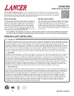
4. Using a wrench, loosen lock nut on the regulator adjustment
screw of the high pressure CO
2
regulator connected to the
source, then using a screwdriver back out lock nut screw all
the way.
DO NOT TURN ON CO
2
SUPPLY AT THIS TIME
NO CONECTE TODAVÍA LA ALIMENTACIÓN DE CO
2
.
N’OUVREZ PAS L’ALIMENTATION EN CO
2
À CE
MOMENT.
!
WARNING
!
ADVERTENCIA
!
AVERTISSEMENT
A. CO
2
Regulator
B. Screwdriver
C. Regulator Adjustment Screw
A
B
C
Dispenser Setup
1. Turn on water source.
2. Open the pressure relief valve located on the remote
carbonator, by flipping up on the valve cap lever. Hold open
until water flows from the relief valve then close (flip down)
the relief valve.
3.
Verify all Bag-In-Box contains syrup and check all
connections for leaks.
4.
Place enough ice in the ice bin to fill approximately 1/2 of the
bin before plugging in the unit.
5. Connect unit power cord to grounded electical outlet.
The dispenser must be properly electrically grounded
to avoid serious injury or fatal electrical shock. The
power cord has a three-prong grounded plug. If a
three-hole grounded electrical outlet is not available,
use an approved method to ground the unit. Follow all
local electrical codes when making connections. Each
dispenser must have a separate electrical circuit. Do
not use extension cords. Do not connect multiple
electrical devices on the same outlet.
!
WARNING
Es necesario poner a tierra eléctricamente el
dispensador para evitar lesiones graves e incluso
electrochoques fatales. El cable de alimentación tiene
un enchufe puesto a tierra de 3 clavijas. Si no se
dispone de un toma eléctrico conectado a tierra de tres
agujeros, use un método aprobado para poner a tierra
la unidad. Al hacer las conexiones, respete todos los
códigos eléctricos locales. Cada dispensador debe
tener un circuito eléctrico independiente. No use cables
de extensión. No conecte varios dispositivos eléctricos
al mismo tomacorriente.
F
ADVERTENCIA
La distributrice doit être mise à la terre électriquement
correctement pour éviter des blessures graves ou une
décharge électrique mortelle. Le cordon d’alimentation
a une fiche à trois branches mise à la terre. Si aucune
prise de Courant électrique à trois trous n’est
disponible, utilisez une méthode approuvée pour mettre
l’unité à la terre. Respectez tous les codes électriques
locaux lorsque vous faites des connexions. Chaque
distributrice doit avoir un circuit électrique séparé.
N’utilisez pas de cordons prolongateurs. Ne branchez
pas plusieurs appareils électriques à la même prise de
courant.
F
AVERTISSEMENT
6. Test the motor operation by pushing the ice chute lever until
agitator motor begins to turn.
7.
Activate each valve to ensure a good flow of water is
achieved.
8. Ensure pump deck is turned OFF before turning on CO
2
.
Failure to disconnect the motor power supply will
damage the carbonator motor, the pump and void the
warranty.
Si no desconecta la alimentación eléctrica del motor
podrían dañarse la bomba y el motor del carbonatado y
anular la garantía.
Le fait de ne pas maintenir le dégagement spécifié
fera surchauffer le compresseur et aura comme
conséquence une défaillance du compresseur
.
!
ATTENTION
!
ATENCIÓN
!
ATTENTION
9. Turn on CO
2
at the source then, using a screwdriver, adjust
the high pressure regulator at the source to 75 PSI (0.517
MPA) then tighten locknut with wrench.
A. Regulator Adjustment Screw
B. Adjust to 110 PSI (0.758 MPA)
C. Wrench
A
B
C
10. Activate each valve until gas-out.
11. Plug in the remote carbonator pump deck, if not already
done so, and turn the switch to the ON position.
12. Activate each valve until the carbonator pump comes on.
Release the button, allow carbonator to fill and stop. Repeat
this process until a steady flow of carbonated water is
achieved.


