background image

Lancer Corp.

800-729-1500

Technical Support/Warranty: 800-729-1550

[email protected]

lancercorp.com

Wiring Diagram - 115 Volt

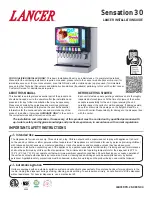
Summary of Contents for SENSATION 4800

Page 1: ...cease operation of the unit and contact authorized service technician Service cleaning and sanitizing should be accomplished only by trained personnel Applicable safety precautions must be observed I...

Page 2: ...attempting any internal maintenance The resettable breaker switch should not be used as a substitute for unplugging the dispenser from the power source to service the unit Only qualified personnel sh...

Page 3: ...eau connect s directement une alimentation en eau potable doivent tre calibr s install s et maintenus selon les lois f d rales provinciales et locales La conduite d alimentation en eau doit tre un tuy...

Page 4: ...t for concealed damage If evident notify delivering carrier and file a claim against the same NOTE 6 If leg kit has been provided assemble legs by tilting unit The drain spider is located to the right...

Page 5: ...nted on top of dispenser do not install dispenser on legs Connecting lines can be run through the back of the dispenser or extend down through a counter cutout NOTE 6 In order to facilitate proper dis...

Page 6: ...lo para que el ice puede moverse sin obstrucci n Contacto con su proveedor de fabricaci n de hielo para informaci n sobre adecuado bin termostato ATTENTION ATENCI N Failure to use an ice bin thermosta...

Page 7: ...de proc der des raccordements lectriques AVERTISSMENT 12 Route drain hose from designated open type drain to fitting on Drip Tray and connect hose to fitting Drain line must be insulated with a closed...

Page 8: ...ting D Oetiker Pliers D A Tee Fitting B Line to Syrup Pump C Fitting D Line to CO2 Supply A B B C D A Syrup Pump Inlet B Fitting C BIB Connector D Oetiker Pliers A B C D Installing CO2 Supply 1 Connec...

Page 9: ...dispensador debe tener un circuito el ctrico independiente No use cables de extensi n No conecte varios dispositivos el ctricos al mismo tomacorriente F ADVERTENCIA La distributrice doit tre mise la...

Page 10: ...t NOTE A B A Water ON B Syrup Closed 3 Using a Lancer ratio cup verify water flow rate 5 oz in 4 sec Use a screwdriver to adjust if needed 4 Remove nozzle by twisting counter clockwise and pulling dow...

Page 11: ...140 F 60 C Puede da ar la m quina expendedora NO vierta soluci n desinfectante en ning n tablero de circuitos Aseg rese de que toda la soluci n desinfectante sea removida del sistema Utilisez des gan...

Page 12: ...all removable parts Ensure agitator clip is locked 14 Fill Unit with ice and replace Top Cover 15 Reconnect Dispenser to power source Refer to the Automatic Agitation Warning on page 3 NOTE D fense d...

Page 13: ...t Residual sanitizing solution left in the system creates a health hazard Despu s de la esterilizaci n enjuague con el producto final hasta que eliminar el sabor que queda No enjuague con agua fresca...

Page 14: ...ot check to see if the solenoid leads are connected to the PC board or damaged check continuity of solenoid Replace if defective D9 This light is on when the motor is activated When the chute is depre...

Page 15: ...CONDS SWITCH AUTO AGITATE OFF TIME 3 4 OFF OFF NO AUTO AGITATION OFF ON 20 MINUTES ON OFF 40 MINUTES ON ON 60 MINUTES To prevent possible harm to the environment from improper disposal recycle the uni...

Page 16: ...Lancer Corp 800 729 1500 Technical Support Warranty 800 729 1550 custserv lancercorp com lancercorp com Wiring Diagram 115 Volt...

Reviews: