


Lake Shore Model 475 Gaussmeter User’s Manual
2-2
Background
The rate at which an analog signal must be sampled depends on the frequency content of the signal. A signal is said to be
properly sampled if the original signal can be exactly reconstructed from the digital information. It turns out that a signal
can only be properly reconstructed if the signal does not contain frequencies above one-half of the sampling rate. This is
referred to as the Nyquist frequency. In the case of the Model 475, the ADC is sampled at 40 kHz in wide band AC
mode. In this mode, the highest frequency signal that can be accurately represented out of Analog Output 2 is 20 kHz
due to the limit of the Nyquist frequency. In this case, Analog Output 1 should be used to monitor the signal.
It should be noted that although the Nyquist frequency will limit the signal that can be accurately reconstructed, it
doesn’t affect the RMS reading of the signal. The energy content of the signal above the Nyquist frequency will be
aliased to lower frequencies where it will be included in the RMS calculation.
2.1.4
Model 475 System Overview
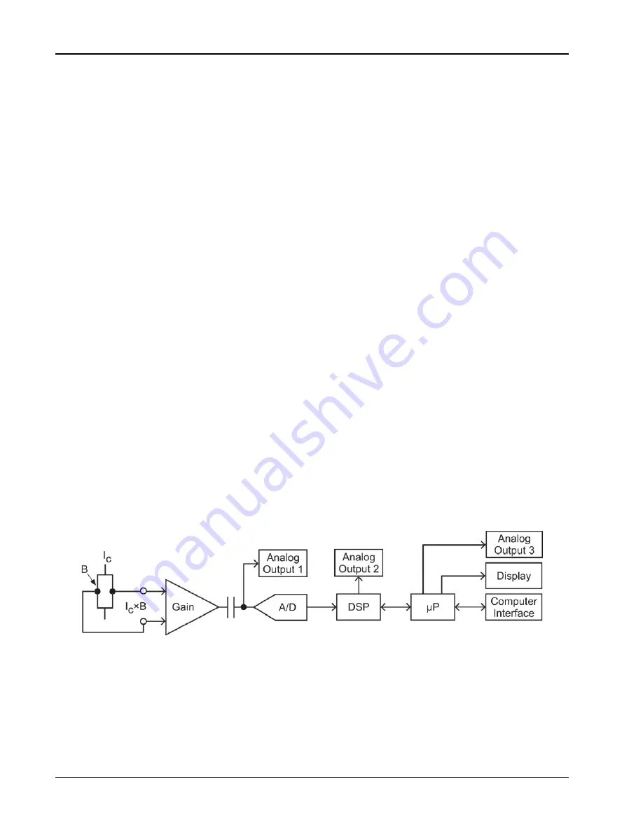
The Model 475 Gaussmeter is a highly configurable device with many built-in features. To better illustrate the
capabilities of the DSP Gaussmeter., refer to the Model 475 system block diagram, Figure 2-1.
The Model 475 uses a 100 mA, 5 kHz square wave excitation to drive the Hall sensor in DC mode and narrow band AC
mode. In wide band AC mode, it uses a 100 mA, DC excitation to drive the sensor. The Hall voltage produced by the
sensor is fed back into the instrument and sent through a programmable gain stage. The signal is then AC coupled into
the A/D where it is read at up to 50 kHz. Those signals are then sent to the DSP where the signal processing is done and
the readings are filtered. The data is then transferred to the microprocessor where the readings can be sent to the display
or out to the computer interface.
The Model 475 has three different analog outputs, each one providing different information. Analog Output 1 is a pure
analog output being taken just before the A/D and is corrected for nominal probe sensitivity. In wide-band AC mode, this
represents the actual signal being generated by the Hall sensor. It is not as useful in narrow-band AC and DC modes
where the output is going to contain the 5 kHz excitation frequency.
Analog Output 2 is generated from a high speed D/A converter controlled by the DSP. This output is generated from the
data after the product detector and is a representation of the actual field being measured. A measured DC field will
appear as a DC signal and an AC field will appear as an AC signal. Analog Output 2 is corrected for nominal probe
sensitivity and probe zero offset.
Analog Output 3 is generated from a D/A converter controlled by the microprocessor. This output has many different
modes of operation including manual output, field control, and to output a voltage that is proportional to the field being
read, including probe zero offset, field compensation, and temperature compensation. If the instrument is set up in AC
mode, then the output is a DC voltage proportional to the RMS value of the field.
Figure 2-1. Model 475 System Block Diagram


