7) PREPARING AND ASSEMBLING THE OPERATOR
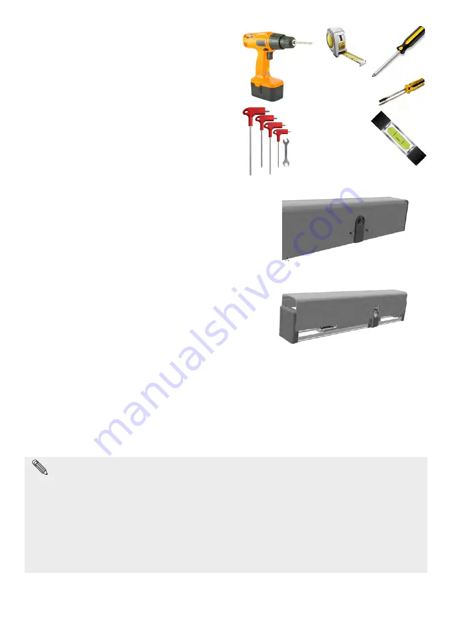
7.1) Required tools:
Tape measure, drill, level, thin flat-head screwdriver, medium-sized
flat-head screwdriver, large cross-head screwdriver, Allen wrenches
with handle (sizes 2.5 – 4 - 5 – 6), flat-head wrench 10.
7.2) Operator control
Remove the operator from its packaging and remove the screws
retaining the cover.
Remove the aluminium cover from its seat, pulling it firmly upwards
and without applying pressure on the sides, if possible.
15
The Neptis SMP operator foresees the possibility of connecting the arm on both sides of the mechanical body and therefore makes it
possible to select the opening movement direction.
Identify the correct side for connecting the pin, based on the type of arm used and the type of operator assembly. Carefully review the
technical drawings in paragraph 5 and the scheme showed in paragraph 8.
The schema in paragraph 8 shows the possible configuration and connection to be performed on NEPTIS SMP drive, depending on the kind
of arm which has been used.
For simplicity, the schema can be summarized in the following points:
Ÿ
Using the
articulated push arm (BSS2)
: install the drive leaving unchanged the factory settings and please check the
assembly instructions on paragraph 5.
Ÿ
Using the
sliding pull arm
(BDT2)
or the
elbow arm
(BSG150/250)
: remove the cover following the instructions described on
paragraph 7.2, and disconnect the motor and encoder cables from the control unit. Connect then cables CL1404 between the
motor and encoder cables you have just disconnected and the control unit. Install the cover once again and follow the
installation drawings on paragraph 5.


